The Ins And Outs Of All-Passive Optical Signal Distribution
In a previous article we discussed optical switching and some of the associated applications. This article will discuss a close cousin to switching, namely optical signal distribution. Optical splitters, available for both multimode and singlemode systems, play an important role in fiber transmission systems. Knowing their capabilities and specifications allows you to implement them in unique, efficient, and effective transport systems for your various applications.
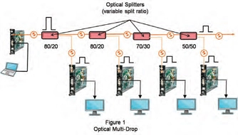
OPITCAL SPLITTERS (variable split ratio)
FIGURE 1: In this digital signage application, the signal (video/audio) is sent to a number of different locations using only one fiber. The in-line optical splitters have various split ratios so that each of the receiver units has approximately the same received optical power while maximizing the throughput signal strength for additional drops down the fiber.
1x2 Splitters: The most common and simplest type of optical distribution system is the 1x2 optical splitter. These devices have one input and two outputs where the signal is split into two optical paths for transmission to different locations. The most common 1x2 splitter is the 50/50 type, which splits the optical input signal into two equal-strength outputs.
Every time the signal is split in half, the signal strength is cut in half or is decreased 3dB from its original level. For example, if the input power to the 1x2, 50/50 splitter is 1mW (0dBm), each leg will have a theoretical output level of 0.5mW or -3dBm. Almost any split ratio can be obtained. Some of the more common types include: 50x50, 80x20, and 90x10. The required split ratio is determined by the application and the optical loss in each leg of the fiber system. In multi-drop applications, different split ratios are typically used to match the received optical power as the optical signal traverses from one drop location to the next.
These 1x2 splitters have many applications in fiber optics, including wavelength-selective devices for transmitting bi-directional signals on one fiber. These devices and applications will be covered in later articles.
1x4 & 1x8 Splitters: These common devices split the optical signal into equal parts, either 4, 8, or 16. Unlike the 1x2 splitters, where different split ratios are available, these splitters are only available in equal split ratios. The optical loss of each of the legs in the splitter is determined by the number of outputs in the device. Every time the signal is split or divided in two, each output or leg has a 3dB attenuation or loss.
In addition to these ‘split’ losses there is also an overall device loss or attenuation do to the inefficiencies of the device. This loss is called the “insertion loss”, and is typically around 1dB to 2dB, depending on the quality of the splitter and the number of output ports on the device..
OPTICAL DISTRIBUTION SWITCHFIGURE 2: A typical schematic diagram for 1x4 and 1x8 splitters.

Because these passive splitters attenuate the signal in each output port or leg, you must take this additional attenuation into account when calculating your overall link or system loss budget. A link loss budget for a typical HDSDI fiber link is around 15dB. This loss budget includes all fiber-related losses, such as connectors, the fiber itself, and any splitters that may be in the link. In this example, since an 8-channel splitter will introduce a per-port attenuation of about 10dB (splitter plus insertion losses), only 5dB is available for all other optical losses— reducing the overall maximum transmission distance.
