Quality of Service Part 4: Configuring an AV Switch in the Real World
This final installment of the Zielie Deep Dive Series on Quality of Service walks you through the concepts, and tasks related to configuring a switch for DSCP marking for the same TMUBPS using the information gathered and decisions made in QoS Part 3.

Part 4: Configuring a Switch for DSCP
In QoS part 3 we gathered the information required to mark DSCP values for unmarked traffic flows for a TMUBPS (Totally Made Up but Plausible Scenario). In this installment we will go through the concepts, and tasks related to configuring a switch for DSCP marking for the same TMUBPS using the information gathered and decisions made in QoS part 3.
Disclaimer
I am not tightly tied to any particular brand, so I read a lot of manuals. I find it frustrating that, between manufacturers, or even between models from the same manufacturer, the same things will have different names and/or different things will have the same names. Often the steepest part of my learning curve on a new product is mentally translating what I already know to the vocabulary used by the new product.
These articles are about technology, not products. I try to use technically accurate and consistent terminology in my descriptions, using the most common terms if there is consensus, and trying to use the terminology of the underlying technical standard where there is not. I attempt to mention when different manufacturers use different terms, but I don’t know them all. If you only use one type of network gear, and they choose to use different words than me, you may have to do some mental gymnastics to recognize both world views.
Switch Configuration for QoS
QoS configurations on a switch consist of three parts. They will often be in three different areas of the configuration user interface.
1. Classify Packets
2. Mark Packets
A daily selection of features, industry news, and analysis for tech managers. Sign up below.
3. Mapping Queues to Markings
4. Scheduling Queues

Classify Packets
In general computing, a Class is a group of objects that share similar attributes. The purpose A DHCP Class to differentiate a subset of the traffic entering the switch from all other inbound traffic so that the specific QoS Policy Attributes required for the class (In this case DHCP markings) can be applied.
The switch identifies the packets belonging to each class by comparing a set of Class Rules, more formally called a Class Definition, to each incoming packet and adding the packets which match the rules to the class.
he class definition is built from a combination of values from the layer 2,3, and 4 network headers. Each header value used in the rule is called a Class Attribute. The table below shows a sample of the header fields which can be used, although exact fields and options available vary from switch to switch.

Classes are intended to be reused so they should be defined as broadly as possible, while still providing differentiation. For example, if you had four devices, each communicating with a HTTP server, you could write 4 rules, with four different source IP addresses all having the same destination IP address, resulting in four classes. A better class definition would be to write a single rule with the destination port of 80 (http) and the server destination IP address and then apply this rule to cover all the devices.
Some fields will allow a range. This is typically specified with a mask, just as the subnet range is specified with a subnet mask. Like a subnet mask, these masks designate the portion of the binary version of the value that needs to match Depending on the manufacturer, masks come in two forms. There is the bitmask which looks and is calculated like a subnet mask, and there is the wildcard mask which is the same information but derived from inverted binary information.

The table above shows some examples of masks in both forms. If you are uncomfortable with calculating masks, you can search the internet for “subnet mask calculator” (for bit masks) or “wildcard mask calculator” and you will quickly find a tool which will give you the mask for your chosen range.
Classifying the TMUBPS Traffic
The process for applying the class definition and adding them to the class will be specific to your switch, but once you understand these concepts it will be easy(er) to follow the directions in the manual.
Using the information from the TMUBPS that we gathered in QoS Part 3 we can build the prog_audio and video classes, along with the class definition listing the class attributes as shown below,
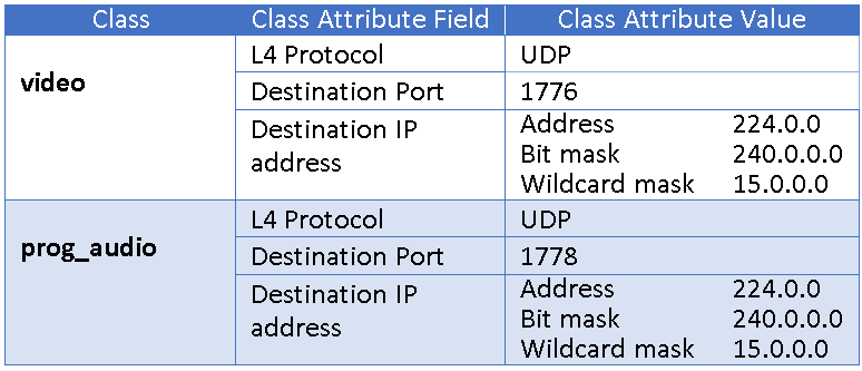
Pro tip>> When we gathered the information, we used a destination IP address range of all multicast (224.0.0.0 to 239.255.255.255). If required, we could use a tighter mask. For example, If I know that my multicast address range was 235.3.100.1 to 235.3.100.35, I could use a mask of (bit mask) 255.255.255.192 or (wildcard mask) 0.0.0.63. The bit mask for a single IP address is 255.255.255.255 (wildcard mask of 0.0.0.0).
Next, using the information gathered from the TMUBPS we will build the class for control communication between the Pretendtron Controller and the Vapor3000 encoders. At first glance it seems pretty straight forward, match on TCP and control port (3000) of the encoders and move on. But there is a twist, this data traffic is two-way.
Because it is using TCP, when the Vapor3000 sends it’s reply to the Pretendtron Controller the source port will be 3000 and the destination port will be the source port the Pretendtron Controller chose in the initial packet. This means we need two class definitions which means we need two classes.
A DSCP Class Map (below) is a group of all the classes that share the same QoS Policy Attributes (in this case DSCP marking to be applied). This allows you to keep track of everything that belongs together and apply the policy to all the classes in the map at once. How this works in practice depends on the methods provided to us by the switch manufacturer and will be discussed later.

IPv6 Note > IPv6 traffic is classified the same way as IPv4 traffic, but because of the different header fields the values to match are different. Generally, IPv4 and IPv6 classes are created and applied separately. If you needed to have a traffic flow that works with either, you will probably need to create a class for each.
Sometimes trusting is just easier In QoS part two we talked about Implementing DSCP (The Easy Way). The easy way turned out to be trusting the source devices to correctly apply the DSCP markings to the packets. In networks as in life, you can’t trust everyone. but if you’re lucky there are some you can trust and this makes the configuration (and life) easier.
When initially enabling DSCP in the switch, there is a setting for whether to trust any QoS markings that are already on the packet. This is generally set to “don’t trust” by default. (a pretty good default in life too). In can be enabled on a per port basis, or globally across all ports on the switch. When you enable trust the DSCP the switch pays attention to the DSCP markings and will use them to assign the marked packets to the QoS queues.
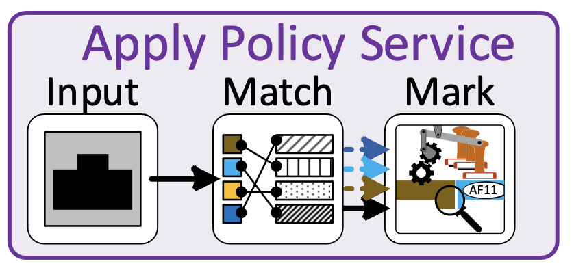
Some switches (NETGEAR, that I know about and probably some others). just won’t act on the DSCP value, but pass do not change the value in the header. Some switches (Cisco, that I know about and probably some others) overwrite DSCP markings on inbound packets to untrusted interfaces with zeros, permanently setting the DSCP to CS0(0). On these switches, you can still do a class attribute match on a DSCP value for an un-trusted interface, because the making process happens after the matching process.
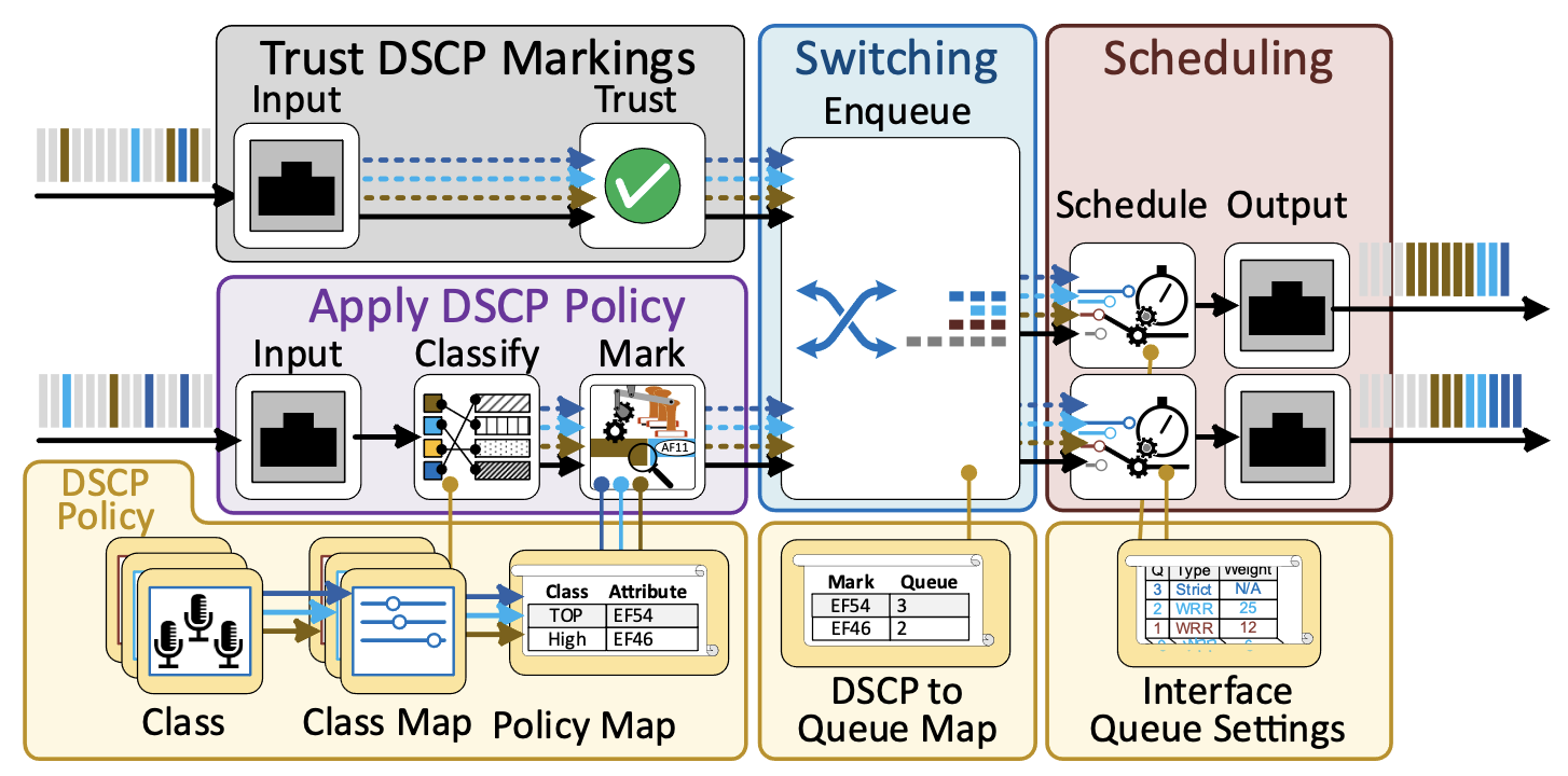
The best solution for our configuration is to not to create class maps for the Dante traffic, but just configure the switch ports connected to the Dante devices to trust the DSCP markings.
Since we are taking care of all the DSCP markings as the come into our switches from the devices. The ports connecting the two switches should be set as trusted. We will discuss our trust issues about the other ports later.
Mark Packets
Now that we have sorted the inbound traffic into classes, we can mark it with DSCP values. We can do this for our TMUBPS by creating a class policy map called av_qos_policy, assigning values to the DSCP Class Policy Attribute for each class map, and applying it to the ingress service interfaces. Easy enough???, no, let’s deconstruct that statement.
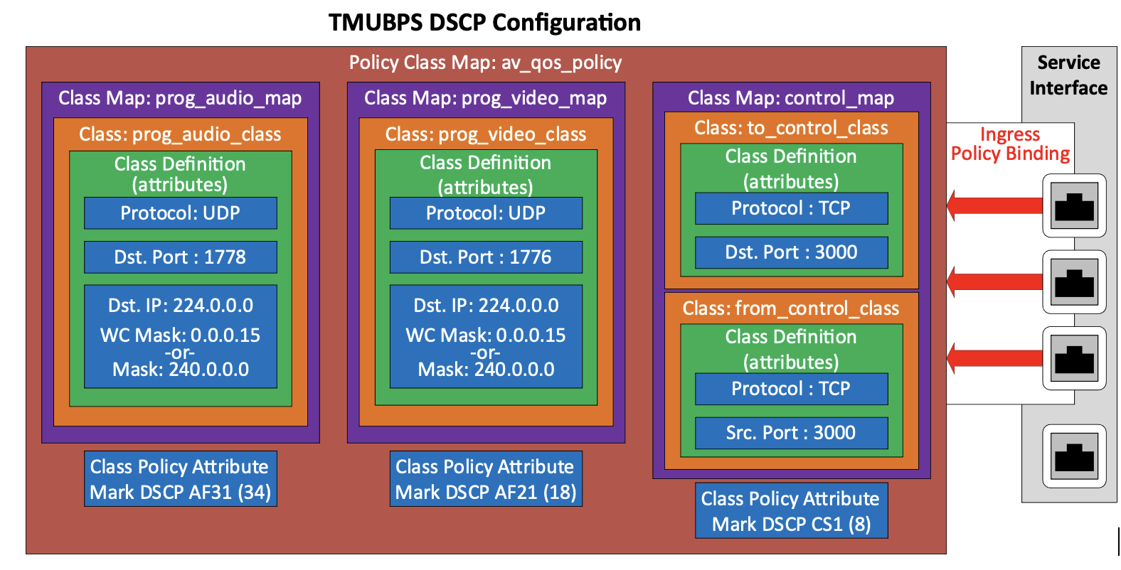
In the illustration above, we show our four classes, defined by policy attributes, and grouped into class maps. Notice that two of the class maps only contain a single class. That is because we could define the entire traffic flow, we wanted to group with a single class definition.
A Class Policy Map is created, and the class maps are added along with the QoS Policy Attributes for each class map. In this case the only QoS policy attribute we are assigning is DSCP marking, but other attributes like bandwidth limiting could be applied. The class policy map must contain entries for all the classes you want to mark on an interface.
Every switch port has both an ingress (inbound to the switch) and egress (outbound from the switch) interface. When referring to network traffic the ingress and egress ports are the physical ports the where the traffic enters and exits the switch.
A service interface is a point in the internal switch traffic flow that the packets can be manipulated using a rule (like a policy or Access Control List [ACL]). Ingress and egress service interfaces are separate and independent.
The class policy map is applied to the ingress service interfaces of the since we are interested in marking traffic that is inbound to the switch. The term applied is used because it means “put into use”. A policy map can be configured and available in advance but applied when needed. A class policy map can be applied multiple switch ports.
At this point the switch will be marking the appropriate packets with the DSCP markings.
Note >> For the TMUBPS example, you could create two policy maps, one with the control, prog_audio, and video class maps to apply to the encoder switch ports and one with control only to apply to the controller switch ports. This would be more work and configuration management and would not accomplish anything meaningful. Generally, a single class policy map is created and applied across all the ports in a switch unless the configuration is very complex (like class definition conflicts), or there is a requirement to treat the class differently from different sources.
Note >> Not all switches supporting DSCP expose (allow to be configured) the egress service interface, so you may not see an “inbound/outbound” choice when applying the policy map to the interface. Egress service interfaces, when available, are used for other QoS functions like bandwidth limits and not DSCP marking.
IPv6 Note > Not all switches support both IPv4 and IPv6 classes in the same policy (The Cisco and NETGEAR switches I use do). In a mixed IPv4, IPv6 environment you may need to choose whether to mark IPv6 or IPv4 packets by having a policy for each. If this is an issue, you will need to choose a different switch.
The Real World
One of the hardest parts of this process is that the procedure and vocabulary used in configuring DSCP policies and applying them to switch ports vary widely between manufacturers and switch models. For example, let’s look at the specific vocabulary and workflow to implement DHCP marking for the two switch brands I deal most commonly deal with, Cisco and NETGEAR.) The fields in the illustrations match the TMBPS configuration.)
In Cisco switches the process starts with creating an Access Control List (ACL) for the class. One or more numbered Access Control Entries (ACE) are added, each defining a class rule by selecting the relevant class attributes. There are separate ACE types for MAC, IPv4, and IPv6 and ACE types cannot be mixed in an ACL so if two ACE types are needed you must create two ACLs. A named class map is created and mapped to the ACL.
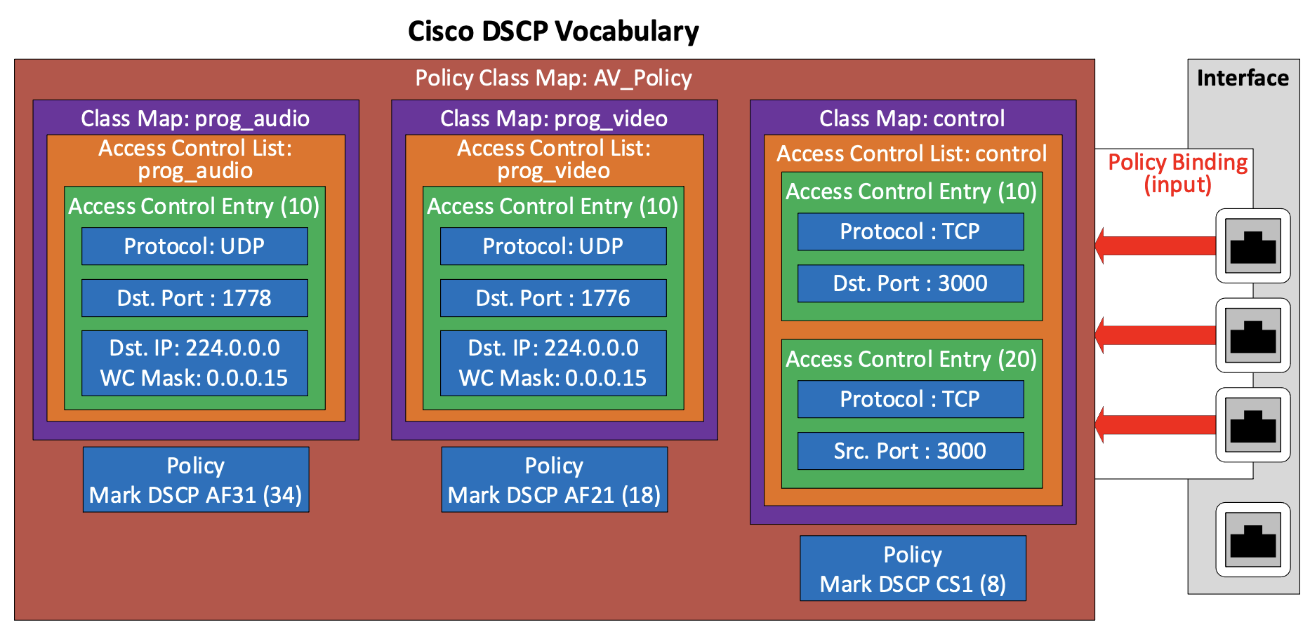
A named Policy is created and then a Policy Map is configured, by adding class maps and setting the Action Type (class policy attribute). The Policy Binding Table is configured to set the policy as the Input Policy (ingress) for the interface.
In NETGEAR switches you start by creating a named class and adding the class attributes to the class in the Class Configuration. There is one class rule (combination of attributes) allowed per (NETGEAR) class. If multiple rules are needed to match the entire traffic flow, multiple classes need to be created and configured.
A Policy are added, and a policy map is created by adding one or more classes. Each class in the policy, has its policy attributes set in the Policy Configuration. (Multiple classes created for traffic flows with multiple rule requirements are given the same policy attributes, effectively creating a class map). The Policy is applied to one or more interfaces in the Service Configuration.
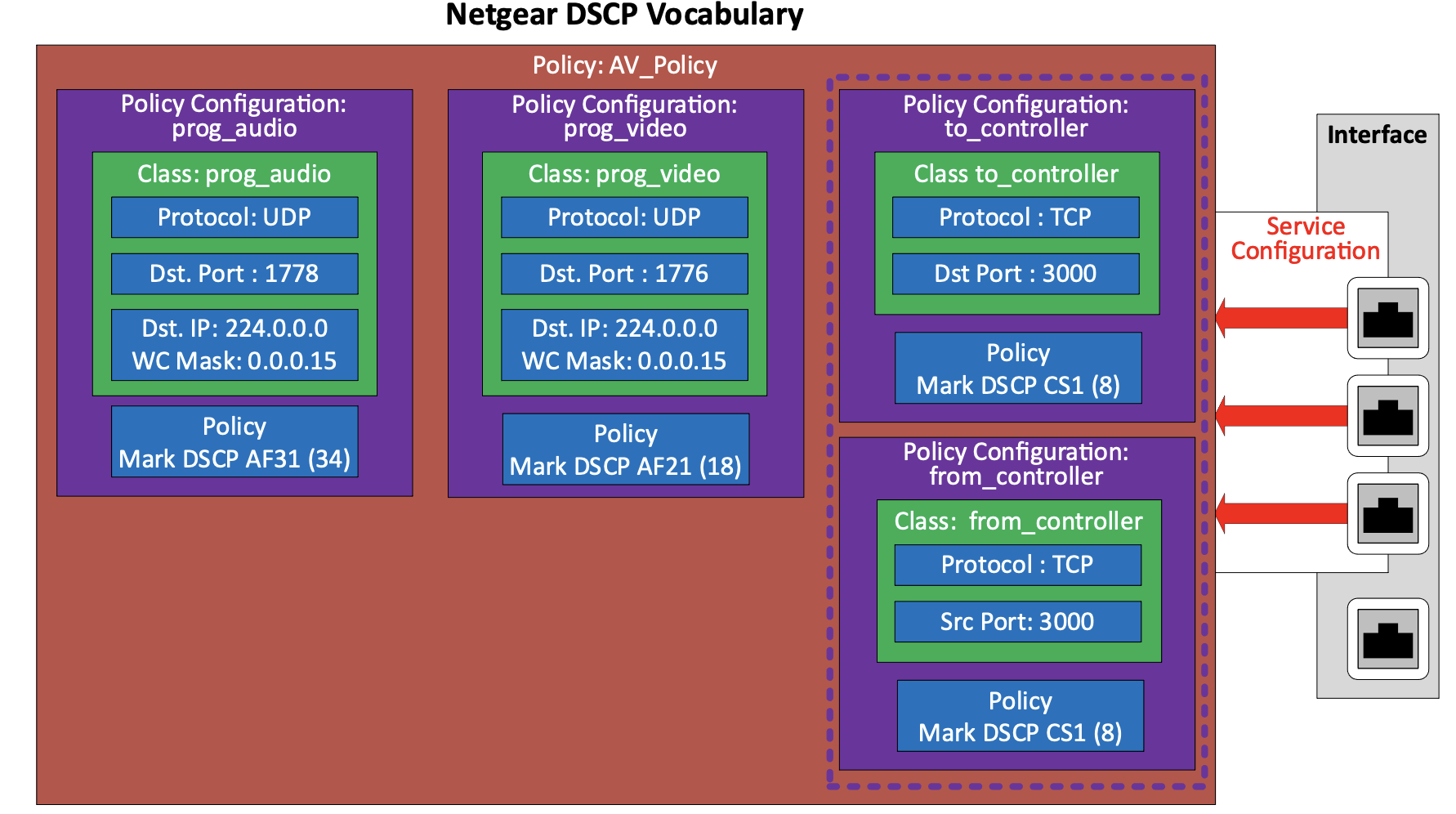
These two examples are representative of the switch market. Every switch manual I looked at was close to one of these schemes. As you can see, the two methods accomplish the same thing, they just vary in process and vocabulary. There is no real advantage to either workflow from a QoS perspective.
Complete the DSCP Config
We are now at the point where we can apply the configurations that set the DSCP markings on the switches. For the TMUBPS, there are two places that we have to make sure the configuration is correct, binding the policy map to the interfaces and making sure the proper interfaces trust DSCP, but first we must decide which interfaces to apply policy to and which to trust. Just like everything else there are tradeoffs.
>> When a policy map is applied to an interface every packet that passes through the interface needs to be inspected. This adds to the processing overhead on the switch. To minimize this overhead, it is best practice to only apply policies to the interfaces that are expected to receive traffic that needs to be classified and marked.
>> If we know that, we do not expect to receive any pre-marked traffic that we want to trust on an interface, best practice dictates that we do not trust DSCP markings on that interface.
Does this mean that we should just trust the interfaces attached to the Dante devices and apply the policy to the control and video devices.? My answer is maybe. I say maybe because this is the AV industry, and these switches are likely to be located somewhere that a kind person “helps me out” by reconnecting Ethernet cables. We have two VLANs, if someone mis-wires the switch and gets a device in the wrong VLAN, we will have a hard failure, and someone will be contacted to troubleshoot it. But if we configure the individual ports on the AV VLAN according to specific QoS settings, someone plugging a device into the wrong port, but on the right VLAN, will cause a soft fault. The system will still work, but maybe not as well as it should.
Soft faults are harder to troubleshoot than hard faults and typically are problems longer before they are reported. Which of these trouble tickets (caused by the DSP being plugged into the wrong port) would make you check to see if the device was plugged into the right port? The hard fault “the DSP doesn’t work” or the soft fault “sometimes audio drops out for a second or so”?
In the table below I show the interface assignments for the TMUBPS, entering may be where the two philosophies diverge.
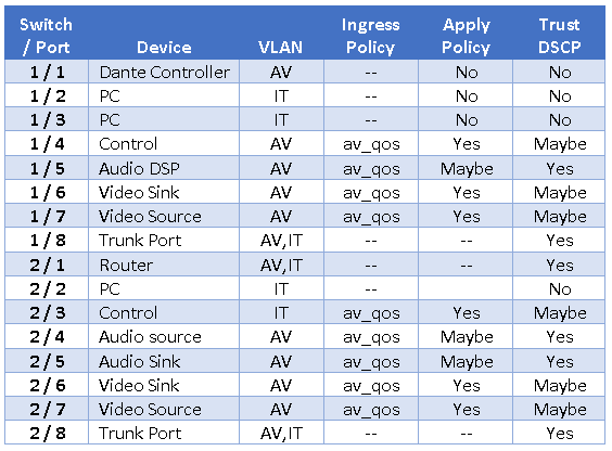
This is a fairly light configuration. My inclination would be to check to make sure I am not near the processing limits of the switch, and then apply the policy to and trust the inbound markings of every port on the AV VLAN (except the Dante Controller) erring on the side of supportability. Essentially, I would change all the Maybes in the table above to Yes and configure it that way.
I would still not apply the policy map or trust the Dante controller, because it is running on a computer. There is no prioritized traffic from the Dante controller and computers are more likely change what they are sending to the network over time, as software is added, and configurations are changed. I would not add the policy map to the trunk ports, because it wouldn’t help anything and if they are mis-wired it would cause a hard fault.
Map DSCP Markings to the Queues – Queuing Strategy
For the TMUBPS, these two steps are the same as and can be found in QoS Part 2 If you are just starting out in the middle of this series, or want to review, please find them there.
Conclusion
I hope this brief four-part series on quality of service for AV applications has helped you better understand the way QoS, and specifically DSCP works and the thought process and techniques involved in getting it to do what you need it to do. I call it a brief four-part series, because there is a lot to QoS that we did not cover at all, primarily in the area of bandwidth control.
There is also a potential rabbit hole to go down in the area of queue weight configuration, foreshadowed in QoS Part 2. I have run into situations where audio is dropped before video, even though the audio is in a much higher queue and consuming less bandwidth because the way Weighted Round Robin works combined with the default WRR weights in the switch. I have amassed a lot of data in the lab, but I don’t really know what to do with it yet.
So, for now, I will leave QoS behind. As I write this I have not yet decided, what subject will be featured in my next Deep Dive, but I have quite a few started. Stay tuned.

Paul Zielie, CTS-D,I is a multi-disciplined generalist with 30 years of experience designing and integrating IT, telecommunications, and audiovisual (AV) solutions.
Over the course of his career, he has had most of the roles in the AV/IT spectrum including customer/end user, IT owner, integrator, designer, managed service provider, distributor, pre-sale specifier, executive, and manufacturer. Because of this extensive real-world experience in every facet of the AV/IT lifecycle, he brings an almost unique perspective on the consequences, both intended and unintended of how product and project features are implemented.
“What I really do for a living is solve problems, little or big, with appropriate technical solutions. I believe that technology is in service to organizational goals and workflow, and not an end in itself, and use that as a guiding principle in my design efforts.”
He is a prolific writer and speaker and was the recipient of the 2015 InfoComm International, Educator of the year and was inducted into the SCN Hall of Fame in 2020. As a consulting solutions architect for AVCoIP LLC, Zielie specializes in working with AV manufacturers to create products that meet enterprise customers' IT requirements.
