Balancing technology and human factors is the key to command and control center design.
To the untrained eye, a command and control center may look like an outtake from an episode of "Integrators Gone Wild."
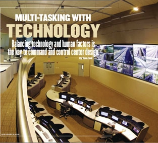
The SunGuide ITS Traffic Management Center (TMC) oversees the operation of the Miami-Dade County Freeway Traffic Management System on a 24/7 basis using a 10- by 31-foot monitoring display wall, allowing flexible and interactive view of more than 40 video sources. centers with their banks of displays assembled into towering videowalls, DLP projection cubes, multiple desktop computer screens, control consoles, track lighting, and curvilinear desks have been carefully constructed. Its elements and the manner in which they're laid out are likely the product of deliberate asset selection, integration, and placement designed to ensure that the space lives up to its name.
Nerve centers and communications hubs for organizations as diverse as utilities, municipalities, telecom companies, pipeline operators, and the military, command/control centers are becoming essential assets. Often manned 24/7 by operators who must monitor, distill, and act upon real-time information, they're built to allow personnel to interpret a smorgasbord of data, images, video, and audio on the fly.
Advanced AV and IT gear plays an essential role. But if it's not carefully selected and properly integrated into the space, taking into account how multi-tasking users process information and factors limiting that ability, even the most sophisticated technology won't allow command/control centers to perform optimally.

the display component. To effectively transmit information to operators, displays must conform to the specific environment.
"Anyone can purchase a bunch of displays, gang them together and call the result a display wall," says Sean LaNeve, director of the Control Room Group of AVI-SPL, a Tampa, FL-based AV systems integrator. "They have to be in the right number, size, and placement so they can be readily seen. You have to understand what operators are going to be looking at."
That's where human factors engineering (HFE) comes into play. An approach that considers how people interface with technology, HFE seeks to tailor that technology to environments in which that interaction is elemental.
In designing a command/control center, HFE can be used to guide selection of AV and IT gear and how the space is laid out and components such as displays, projectors, consoles, and lighting are integrated, says Robert Chamberlain, president and CEO of Monterey Technologies, Inc., a Monterey, CA, a human factors engineering consulting company that assists clients in designing command/control centers. Assessing expected tasks, workload requirements, and human interactions in an environment helps determine functional requirements like personnel, facility layout, and technology tools, he says.
"If good HFE work is applied to the design of a product or system, resulting in the ability for users to understand it more quickly and easily, and to get all of the capability out of that system, then HFE has done its job," he says.
Using HFE and other considerations - budget, targeted function, expandability, and even the "wow" factor - command/control center designers can assemble a plan of action off a fairly standard product template. As all are heavily visuals-oriented, displays and associated components are high on the typical command/control center's AV gear shopping list.
PROCESSOR POWER
Since most incorporate video walls comprised of multiple flat panels or projection cubes, gear, and associated software that manages how content appears on the displays is essential. Multi-image display processors capture content from multiple sources and arrange it as needed on a display wall. A subset, multiviewers, permit the assembled multi-image display to be routed as configured to multiple locations.

Pacific Gas and Electric Company's display wall at their Grid Operations center is viewable from anywhere in the room. technical services for Hoffman Video Systems, a Glendale, CAbased integrator with command/control center expertise. "Taking 200 or more inputs and mixing and matching them for display in the correct resolution can require a processor costing anywhere from $150,000 to $1 million."
New generations of processors are giving centers more content display options. Avitech International Group of Redmond, WA, has developed proprietary techniques to combine multiple high-resolution computer images and high-definition video signals. According to company president Morris Gong, "The biggest growth area for command/control centers is an increasing number of computer images and the addition of HD-SDI signals to the mix." But combining these image types can be tricky. "A scaling algorithm applicable to video may not be as useful for a still image," says Gong. "For video, temporal values are equally as critical as the spatial ones."
With demand for video on display walls growing, Jupiter Systems, Hayward, CA, has unveiled PixelNet, a packet switching-based solution for distributing high-resolution, real-time video in command/control centers. Conceived as an adjunct to Jupiter's Fusion processor, it's now offered as a standalone. It uses a switch-connected node configuration to deliver a high degree of flexibility for selecting and routing sources, as well as how they're displayed.
"Video distribution can grow, shrink and change as needed much more easily," says John Stark, director of product management.
EFFECTIVE SYSTEMS
Whether functioning as part of a video wall or a standalone, a projection cube, LCD, or plasma display must be capable of delivering images that can be easily seen in environments where variables like ambient lighting, sight lines, and user eye strain come into play. Key control factors are brightness, contrast, resolution, intensity, color reproduction, and calibration. (See sidebar, "Display Considerations.")

- to match up as perfectly as possibly - is especially important in a multi-display environment," says Pratt. "We do signal impedance tests that ensure images line up to the naked eye and we also use edge blending technologies."
- While processor and display technology allows ever larger and "busier" videowalls, designers should employ HFE to guard against overloading operator circuits. But the threshold can be fairly high, says Chris Thomasen, a designer with Audio Visual Technologies Group, Stafford, TX.
- "Some clients want up to 12 images on a screen," he says. "When you're confronted with that many on one screen and there's maybe eight screens in play, all going at the same time, your first thought is, 'Wow, how can I take that in?' But it's like driving a car. You learn how to use it."
- Advanced control systems that are highly intuitive, from suppliers like AMX and Crestron, can go a long ways toward improving functionality, Thomasen says.
- Reliability and serviceability are other important factors in display selection. In critical command/control environments, displays can't be down. That's made three-chip DLP projectors popular.
- "LCDs can burn out and single-chip DLPs are not as reliable," says Pratt. "Three-chip DLP projectors are more expensive, but if you're running it 24/7/365, it'll deliver 8,000 continuous hours."
- In applications where such projectors aren't feasible, Pratt adds, it's vital to have an inventory of backup displays or cubes that can be readily activated, as well as a display wall
configuration that's easily accessible.
While command/control centers have to guard against failing displays, power outages pose a more menacing problem. Designs must factor in backup power, control of equipment-generated heat with adequate cooling systems, and UPS devices. With its distributed architecture, Jupiter's PixelNet reduces the impact of a power interruption.
"Single-box processor systems leave centers more susceptible to power outages," says Brady Bruce, Jupiter vice president of marketing. "If an input or output in PixelNet fails, that node can simply be replaced with a spare. The rest continue to operate."
Indeed, the margin for error in command/control centers is slim. That's why their advanced technology is needed for functionality, not show. And it's why managers who oversee their design and implementation must make sure that the chosen technology fits the function and complements, not confounds, those who operate them.
"Although a lot of technology is brought to bear to give people access to information in this decision support system application, the reality is that the intent of any design is getting to the point of intuitive functionality," says Bruce. "It needs to be effective, yet simple."
Tom Zind is a freelance writer based in Lee's Summit, Mo. He can be reached at tomzind@att.net. Got a comment? Contact us at AVT@nbmedia.com, and type the title of this article into the subject header.
Display Considerations
Since many command/control installations operate 24/7, operators may spend an entire shift in front of the displays. So it's important that the information displayed is easy to read with minimal eyestrain. The system designer must match videowall components to the environment to achieve the optimal level of brightness and contrast.
FACTORS IN DETERMINING BRIGHTNESS REQUIREMENTS
The brightness (or luminance) of a videowall is measured in foot-lamberts or candelas per square meter (nit). One footlambert
is equivalent to 3.426 nits. Many videowalls are designed using tiled projection displays (or "cubes") to encase individual projectors utilizing higher performance Digital Light Projection (DLP) technology. These structures allow for "seamless" imaging of several projection devices to create one continuous display wall. The factors that affect the brightness requirements of a videowall system include: Ambient light conditions Projection system brightness Contrast ratio.
AMBIENT LIGHT CONDITIONS
Room lighting should be balanced with the luminance of the videowall in order to minimize operator fatigue and eyestrain. It's important to have a moderate level of ambient light. Typically it is recommended that control room lighting is between 20 to 30 foot-candles (200 to 300 lux). A good practice in control room lighting is to use diffusive lighting. If spot lighting is required, it should be directed away from the display wall, not toward it; otherwise contrast aberrations and reflections may be visible on the videowall.

PROJECTION SYSTEM BRIGHTNESS
In a rear-projection display wall, each projector has a specified brightness level, measured in ANSI lumens. The total combined
projectors lumen level, along with screen size and screen gain, are used to calculate the videowall brightness level. This measurement is specified in foot-lamberts or candelas/m2 (nits). Screen gain is a factor in determining brightness because
of the unique transmissive characteristics of rear-projection display screens. Screens with higher gain factors will exhibit higher brightness. Also, the screen brightness drops as you move off-axis, and this drop may be far more abrupt in a higher gain screen. Typically lower gain screens have a wider viewing range, making the drop-off less abrupt. Therefore, depending on the screen types used and the position of the operators in the control room relative to the screen, brightness and contrast can vary significantly. Typical display brightness in 24/7 control rooms is between 150 nits (minimum) and 500 nits.
CONTRAST RATIO
There are two methods for measuring contrast ratio: "full field" and ANSI. For the full field measurement, an entirely black image is displayed and its brightness is measured. Next, an entirely white image is displayed and its brightness is measured. The ratio of white measurement over the black is the full field contrast ratio. Typically, the full field contrast ratio measurement should be at least 1,000:1. However, a more useful and practical contrast ratio measurement is the ANSI method. The ANSI method measures the black and white levels but does this with a "checkerboard" pattern. Actual contrast values may be much lower than the full field method because of the "light spill" from the white "checkers" onto the black. This measurement better represents the actual contrast performance of the system. A level of >450:1 ANSI is the minimum recommended considering current technologies. See figure 1. Another important design consideration is "system contrast ratio." System contrast ratio takes into account the overall room situation, considering both the videowall itself and the ambient light at the wall. The ambient light at the wall is measured in foot-candles (imperial) or lux (metric). This information is used along with the videowall contrast ratio to calculate the final system contrast ratio. The higher the ambient light level, the lower the system contrast ratio. A minimal acceptable system contrast ratio is 10:1. Typically a design target is 100:1.
[ Source: by Jim Gavloski, Christie Digital]
