DVI HDMI Signals Over Twisted-Pair Cable

A daily selection of features, industry news, and analysis for AV/IT professionals. Sign up below.
You are now subscribed
Your newsletter sign-up was successful
Advances in cable, connector, and driver designs make it possible to send DVI and HDMI signals over longer distances.Now that sending RGB analog video long distance over Cat 5 is well accepted, it seems only fitting that
DVI and HDMI are next. Accomplishing such a feat seems almost magical considering the challenge of simply buying a good quality dedicated DVI or HDMI cable. A fundamental understanding of the challenges and guidelines of DVI/HDMI transmission is necessary in order to take full advantage of long distance extender systems.
WHY THE DIFFERENCE IN CABLES?
The original DVI and HDMI cables satisfied a limited-distance interface. For DVI, the interface is usually from the computer graphics card to the monitor. For HDMI, the interface is typically from a DVD player or AV receiver to a home TV. In each case, no more than about 6 feet is necessary, and certainly no more than three times that distance for typical uses. Within this realm, cable construction employs wire gauges smaller than the 24 gauge wire in the typical UTP cable. Twisted-pair wire size in those dedicated cables ranges from about 28 gauge to 32 gauge. This step-down in wire size yields substantial additional cable loss and is manageable only for short distances. Why use it? Small wire size makes for small diameter, flexible, easy-to-handle cables.
Some DVI and HDMI cables support distances to 75 feet or so, but the physical diameter is significantly larger. These designs often use 22 gauge wire and lower-loss dielectric construction. Larger wire size translates to larger overall diameter and stiffer, heavier cable. With proper active equalization circuits (cable drivers or equalizers) extension to 200 feet is possible.
It's important to remember that DVI cables historically extended only about 5 meters. Release of the HDMI specification ushered in the notion of 75-foot transmission distances as if the standard or the electrical interface somehow improved. In truth, nothing changed. Both specifications include the same electrical requirements for signal transmission. So why is 75 feet promoted in HDMI? After much complaining about short DVI cable distance capability, cable manufacturing improved to the point that this distance is possible under the same specification.
A SKEWED NOTION
Knowing this DVI/HDMI cable history, the notion of transporting DVI and HDMI over low-cost category cabling may seem technically troubling, but it is possible. Successfully sending DVI and HDMI signals over Category 5e, 6, or 7 cable is possible with special cable drivers for two reasons: [1] Those cable driver/receiver circuits are designed for 100 meters distance; and [2] Wire gauge for UTP starts at 26 AWG, with most being 24 gauge, and the better cables as large as 22 gauge. UTP cable works with network systems because it employs differentially driven wire pairs along with varied twist rates that minimize data crosstalk.
Integrated circuit manufacturers invest heavily into IC designs capable of the varied demands of network cabling and its increasing transmission speeds. But while the varied twist rates for pairs within a cable assembly minimizes crosstalk, it also creates timing skew. ICs driving DVI/HDMI transition-minimized differential signaling (TMDS) data over UTP cable must compensate for the timing differences between pairs, as well as attenuation variation. Migration of transmission speeds for networks has necessitated flexibility in cable transmitter/receiver IC combinations. AV applications can take advantage of this technology to exploit DVI and HDMI over inexpensive twisted-pair cable.
A daily selection of features, industry news, and analysis for tech managers. Sign up below.
CHALLENGING CABLE SPECS
Using available network cable driver technology, 24 gauge UTP cable can transport DVI and HDMI over modest distances of about 100 to 150 feet. Why not farther? It's not that cable drivers cannot overcome the attenuation of longer cables, but that crosstalk between pairs impedes the receiver's ability to recover data. Even with the best 23 gauge UTP cable, crosstalk effects ultimately take over. In addition, most receiver blocks available with built-in equalization are limited to about +40 dB, a gain of 100. As receiver gain increases, crosstalk effects magnify.
With increasing cable length, crosstalk rises and gain decreases. As attenuation and crosstalk approach intersection, receiver circuitry can no longer recover clock or data due to crosstalk interference; thus, data recovery becomes increasingly difficult and eventually fails. As the margin narrows to less than 10 dB, transmission failure becomes imminent.
While shielded cable (STP) might help, the cable is only part of the problem. A significant contributor to the crosstalk issue is the RJ- 45 connector. Parasitic capacitance between connector pins provides significant cross-coupling that exacerbates the problem.
So, fundamentally, we see that the parameters affecting UTP transmission distance are cable attenuation and collective crosstalk. Receiver system gain attempts to overcome cable attenuation while its equalizer adjusts to counteract the slope of cable attenuation over various frequencies.
The perfect equalizer system creates a "mirror image" of the cable attenuation curve to enhance the receiver's gain characteristic.

to actively control receiver gain at high frequencies in order to compensate for cable loss. In digital transmission, this is important since the receiver attempts to level the signal amplitude so that the data bit edge detector (or slicer) can do its job.
Cable equalizers have a finite range of compensation capability and are tailored for specific cable types. The serial digital interface (SDI) equalizer is usually designed for specific types of low-loss coaxial cable. For DVI and HDMI, equalizer designs center on twisted-pair cable, whether it may be a dedicated cable or generic Category-style UTP/STP cable. The compensation gain curve (or transfer function) attempts to fit most applications, although it usually is not perfect due to all the cable variations.
Why all the fuss with leveling the received signal? The purpose in all this processing is to present the data signal to some form of detection and recovery circuitry for data reconstruction. One common form of reconstruction is the "data slicer." Data slicers are basically comparator circuits that "look" for edge transitions in the digital data stream by centering the signal on an average DC level, then triggering a threshold comparator to change state as positive-going and negative- going data transitions come along. When the signal level is not equalized, the average DC value drifts around the data slicer set point and this movement is translated at the output as increased signal jitter. Too much jitter corrupts clock and data recovery.
STP TO THE RESCUE
For a modest cost increase, STP cable greatly extends transmission capability. Even with construction enhancements in Category 6 UTP cabling extending network performance to gigabit bandwidth, the effects of crosstalk eventually overtake any performance gains. Shielding and grounding the pairs significantly reduces near-end and far-end crosstalk. Crosstalk elimination extends receiver gain and equalizer performance to their full limit. STP is mandated for Category 7 and ISO Class F and FA. STP cabling supports 600 MHz and 1,000 MHz signaling, thus extending performance from one gigabit to 10 gigabits over a 100 meter link (see sidebar).
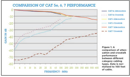
How does STP compare on attenuation and crosstalk to UTP? Figure 1 compares attenuation and crosstalk values for Category 5e, 6, and 7 cables. First, consider the large margin of crosstalk between the Cat 7 crosstalk curve and both the Cat 5e and 6 crosstalk curves. The difference is on the order of about 30 dB. It is obvious that shielding will help us extend transmission distance substantially. Also note the large difference in frequency range. The Cat 5e curve stops at 100 MHz at the TIA network standard limit for that class of service, while Cat 6 service extends to 250 MHz. Of course, these cables do not stop performing at higher frequencies. It is necessary to extrapolate their performance, or measure it, to determine how they work in the application. We see an improved crosstalk margin for Cat 6.
Lower crosstalk curves indicate better performance on the graph of figure 1. Cat 7 service extends to 600 MHz in this data example. Even at 600 MHz, the attenuation to crosstalk margin for Cat 7 is about 20 dB.
MORE LESSONS FROM FIGURE 1
The data used to create this graph was normalized to represent a 100- foot cable. Why? Extending DVI or HDMI over Cat 5e cable is effective to about 100 feet; perhaps a bit longer with Cat 6 cable. With 22 AWG Cat 7 cable, DVI or HDMI 1.2 may function to the full 100 meters. Since the Cat 5e standard stopped at 100 MHz and the nominal distance is 100 feet for extending DVI/HDMI, this length provides a reasonable point of comparison.

.Figure 1: A comparison of attenuation and crosstalk performance between different category cabling types. Data is normalized to 100 feet of cable. clock frequency is 165 MHz. Transmission at 1.65 Gbps means that we need to be concerned about the fundamental at one-half the data rate, or 825 MHz. This makes transmission more complex because the video/audio signaling bit rate is ten times the clock rate. Although the clock frequency does not carry video information, it's important in this discussion to provide simplified insight into the basic challenge that long UTP and STP network-style cabling presents. The actual attenuation and crosstalk performance is governed by the actual loss effects at one-half the video data symbol rate, which is 825 MHz for standard DVI/HDMI and 1.7 Gbps for HDMI Category 2 performance. These frequencies are well beyond the standard data specifications for network cable. Therefore, transporting DVI and HDMI over long twisted-pair cables requires some "command of the art," so to speak. Pushing performance requires one to pay careful attention to the matching of network cabling to specific drive ICs along with careful signal processing and board layout in order to handle these extreme data rates needed for DVI and HDMI.
Figure 1 shows that, for the 165 MHz clock, the Cat 5e cable will have attenuation and crosstalk approaching intersection with a very small margin. The 825 MHz associated with the bit rate is way beyond the usable range based on the attenuation and crosstalk curves. Certainly, the clock signal just falls inside the usable range. What gives? How does it work at all?
By the time video/audio data completes the journey through 100 feet or more, the UTP cable's low-pass filtering effect reduces the data symbols to mere sine waves. This is where the receiver's gain and equalization range become important. Physics works in our favor since the rise and fall time on the data signal diminishes, so does a proportionate level of crosstalk. Remember that we need at least a 5 dB margin. With careful receiver design and board layout, 100 feet is just attainable for DVI and HDMI. Cat 6 cabling provides us additional margin due to its 250 MHz specification, or, more distance with the same margin. At 165 MHz, Cat 6 margin is about twice that of Cat 5e cable.
The Cat 7 STP cable exhibits very ample margin at 165 MHz. In fact, considering HDMI 1.3, an HDMI Category 2 cable design supporting the 340 MHz clock and 3.4 Gbps data channel still has almost 30 dB margin at 100 feet. In addition, we can extrapolate past the 600 MHz limit in the chart to realize that Cat 7 has possibilities with the one-half signaling rate, or 1.7 Gbps. Now, crosstalk is no longer the main issue, but attenuation and available receiver gain become the limiting factors.
Consider for a moment the slope of the Cat 7 attenuation and crosstalk curves in figure 1. Due to the wide margin between attenuation and crosstalk at the 340 MHz clock rate, regular DVI and HDMI implementations at distances to 100 meters are possible. Our current experience shows we can transport DVI or HDMI on 26 AWG Cat 7 STP to about 200 feet. With 22 AWG STP cable, we have transported DVI and HDMI a full 100 meters, or 328 feet.
OH, YES, THE CONNECTORS
Just as connection systems play an important role in network systems bandwidth, they are no less important for transporting DVI and HDMI data. From the previous review on signaling rates for these video interfaces, it's obvious that the selection of RJ-45 modular connectors will impact electrical losses. The standard RJ-45 connector contributes additional crosstalk between data pairs by virtue of its construction.
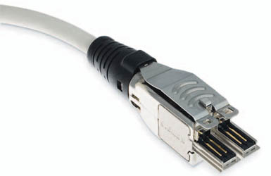
A new connector system was recently adopted for Category 7, or ISO Class F, service. Network cabling manufacturer Siemon offers the new TERA connector to support 600 MHz and above. The TERA connection system provides significant isolation between data pairs with radically different construction. Crosstalk budget greatly exceeds that of Category 6 (or Class E) service. The TERA connector will support us into 10 gigabit Ethernet.
The TERA connection system along with 22 AWG shielded twistedpair cable supports Category 1 DVI and HDMI data rates up to 100 meters with significant headroom. If you find yourself in a situation where you need some additional distance with existing extender systems, using Cat 7-style STP cable will reduce crosstalk significantly and perhaps provide the distance boost you need. Try substituting it for only the primary video/audio data cable between the transmitter and receiver.
CAT WITH AT LEAST 9 LIVES
Despite advances in both fiber optic and wireless technologies, copper cabling will likely be with us for some time to come. During research for this article, I uncovered discussions on Category 8 proposals, which solidly identify 1.2 GHz as the next step in network data rates over twisted-pair cable. How about Cat 9? Does this Cat have more than nine lives? With improvements in digital data interfaces and connectors, the future of copper cabling remains very bright indeed.
