An Inside Look At All-Optical Switch Applications
by Ed Miskovic
One of the key aspects of fiber optic systems is their ability to be much more than simply a replacement for copper. Understood properly, fiber system topologies are significantly more versatile than their copper counterpart. The telecom industry has understood and embraced this feature for many years and, as a result, has created some of the most unique and versatile fiber system architectures available. All of the high-tech fiber elements and systems in the AV market are derived directly from the telecom industry.

Figure 1: 1x4 all-optical distribution switch
Optical switching, distribution, and routing play a very important role in these all-optical system designs. It’s important to understand how these optical switching systems can provide the AV market with signal transport capabilities never before realized in traditional copper infrastructures. This article will focus on all-optical switching and routing technology and applications and how they can enhance your system capabilities and flexibility.
As a point of reference, OEO (optical- to-electrical-to-optical) switches have been around for a number of years and have gained acceptance in the AV market, primarily because the switching fabric and technology are well understood. Basically, the optical signal is received at an input port on the switch, converted to an electrical signal, switched then converted back to an optical signal for further transport or distribution over fiber.
All-optical switches perform many of the same functions as the OEO switches but have other features and capabilities not available in OEO switches. A previous article addressed some of the basic optical switches. This article will briefly review a couple of these and expand on the all-optical switch, its features and capabilities.
The key advantage of all-optical switches is that they are signal type, signal quantity, data rate, and in many instances, direction and wavelength agnostic.
1x4 Optical Switch: This is a basic all-optical switch module that has multiple system applications. It can be used to route any type of optical input signal to any one or all four optical outputs simultaneously using standard RS-232, USB, or ethernet commands. In secure military or government applications, this switch can be used to route information to specific outputs that may have different security clearances. For example, if the signal were to originate as an unclassified signal, all outputs could be switched on to receive the input signal. If, on the other hand, the input signal were to be a secure, classified signal, only those outputs channels that are authorized to receive these classified signals would be switched on, leaving the unclassified outputs off. The switch software would provide the intelligence to control each output according to its classification rating.
Because these switches are alloptical, there is no need to convert the signals to electrical for switching. Since the signals stay in the optical domain, the information maintains its optimum quality and security. This all-optical feature also means that, unlike an electrical switch equivalent, any type of signal and data rate can be switched in this single optical switch.
Other system applications such as small courtrooms can benefit from this type of switch, where the judge may have control over it. For example, the video input may be from some type of evidence or document camera. The judge would have control over who has access to this information such as the jury, gallery, media, etc. and can select to whom the information is delivered.
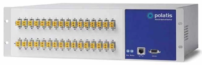
Figure 2: 32x32 all-optical matrix switch from Polatis
NxM All-Optical Matrix Switch: On a much larger scale, the alloptical matrix switch represents the ultimate transition from copper to an all-fiber system architecture. The OEO switch certainly has its place in system designs but the all-optical switch is becoming a formidable alternative—once it is properly understood and implemented in system designs.
There are basically two types of all-optical matrix switches, those with and those without dithering. Dithering provides feedback to continuously optimize the coupling between the input and output ports of the switch. Basically, a small amount of light is coupled from the output port and used as a control signal to move the switch alignment mechanism—typically a MEMs (MicroElectroMechanical) device. By continuously monitoring and adjusting the position of the MEMs mirror, maximum coupling efficiency is maintained. The result of this continual adjustment is a very small amount of optical coupling variations, necessary to actively control the switch’s port alignment. In digital systems, this is not of concern. However, in analog transmission systems, such as RF systems, this dithering signal will mix directly onto the RF or analog signal adding to the signal noise floor thus obscuring low-level signals of interest. This dithering also limits the ability of each port to switch bi-directional signals. Switches that do not rely on dithering provide a more stable output compatible with both digital and analog signals and can be used to switch bi-directional optical signals over one fiber.
The OEO switch incorporates optical I/O ports but does the switching via an electrical switch. The input signal is first converted to an electrical signal where it is sent to the switch fabric and then converted back to an optical signal at the output port. As the name implies, the all-optical switch requires no such electrical conversion providing a more versatile switch. One fundamental difference between the OEO and all-optical switch is that, on its own, the all-optical switch cannot be used as a broadcast switch. That is, any input can be mapped to only one output at a time.

Figure 3: photonic multicast
Enter Photonic Multicasting. As previously mentioned, having signals in the optical domain opens up a new understanding of system design. Photonic Multicasting basically takes an output, splits that output and distributes it to a number of other switch inputs. Each of these can be switched to its own mapped output providing a form of multicasting or broadcasting.
Once the input channel is switched to the multicast port, that signal is then split into multiple, identical signals and routed to specific switch inputs. These inputs can then be routed to any output port—allowing for one input to be broadcast to multiple outputs.
As the multicast signal is split into multiple channels, the optical power is subsequently attenuated. A 1x4 splitter will introduce 6dB of optical attenuation while a 1x8 splitter will yield an attenuation of approximately 10dB. In many system designs, this additional attenuation can be tolerated by the equipment’s optical loss budget. However, in some more elaborate systems, this attenuation may be too high for the overall system loss budget. This signal loss can be compensated with the addition of an optical amplifier prior to the splitter.
Prior to being split, the optical signal from the multicast port is amplified with a gain comparable to the attenuation of the optical splitter. For example, if a 1x4 splitter is used, the optical amplifier will have a gain of 6 dB to compensate for the 6 dB loss insertion loss of the splitter. In this way, the output single amplitude of the multicast ports will be approximately the same as the point-topoint output ports, preserving the system’s optical budget.
This photonic multicasting property allows the all-optical switches to compete directly and more efficiently with conventional OEO switches with enhanced versatility and security.

Figure 4: photonic multicast with amplifier
The OEO switch has its place in the AV market and is seeing increased use. As with any conversion process, there are always some artifacts or anomalies generated when converting from one format to another (optical to electrical and back) leading to increased errors and system degradation. All-optical switches do not have such anomalies and maintain the signal’s high quality throughout the switching process. They also have much higher application potential since they are protocol, data rate and direction agnostic. As shown in this article, the all-optical switches help define the advanced role of fiber in the AV market and further illustrate the fact that fiber is significantly more than just a replacement for copper. Once system design engineers gain a better understanding of these technologies, their applications, advantages and the diverse capabilities of fiber, you will see increased and far-reaching AV applications using this technology and at a lower cost.
Matrix Switch Characteristics
- Electrical-to-Optical-to-Electrical (OEO)
- ■ Converts signal to electrical for switching
- ■ Lossless switching—Retimes, reclocks and regenerates signals (at specific data rates)
- ■ Unidirectional switching
- ■ Point-to-point and broadcast mode
- ■ Specific digital date rate formats
- ■ Available up to 1024x1024 (and higher)
All-Optical (OOO)
■ Keeps signal in optical domain, additional security
■ Lossy switching—Optical insertion loss from input to output
■ Bidirectional switching
■ Point-to-point and broadcast mode (using photonic multicasting architecture)
■ Data protocol and rate agnostic
■ Max input/output typically 256x256
Ed Miskovic (emiskovic@meridiantech. com) is EVP of sales and marketing for Meridian Technologies.
