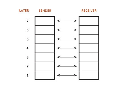
Figure 1: Peer to Peer The concept of layered communications is at the foundation of all IP communications, including audio and video over IP. Within a TCP/IP system, functional tasks are separated into layers. This procedure greatly increases interoperability among systems.
There are at least two popular layered models, the seven-layer model developed by the International Standards Organization (OSI), and the five-layer Internet model. They operate on the same set of principles. These are:
• A function assigned to Layer n of a sending station will also be a task of Layer n in the receiving station.
• To send a message, Layer n delivers its message to Layer n-1. Layer n-1 attaches a header and appears to send the message to its counterpart, Layer n-1 in the receiver. The header is interpreted and stripped and the message is passed to Layer n in the receiver.
• Layer n in the sender assumes its message is for the same Layer in the receiver. This is called peer-to-peer communications and is illustrated in Figure 1.

Figure 2: Layer 4 to Layer 4 As an example of the second principle, TCP is referred to as a Layer 4 protocol using either the OSI model or the Internet model. IP is a Layer 3 protocol. Refer to Figure 2. In the sender, the outgoing TCP segment (message) is handed to IP. The IP function attaches a header that has the receiver’s address in it. The combination, now called a packet, is sent through the network to the receiver’s IP software. There, the header is removed and interpreted and the received segment is passed back up to TCP at Layer 4.
In peer-to-peer communications, each function in the sender has, at the same level, a corresponding function in the receiver. For example, that’s how we know the Layer 2 network card address is interpreted by the Layer 2 function of the switch or router. It’s also how we know TCP sequence numbers will be read and used by the receivers TCP software. Even standards committees delegate their tasks based on the Layers at which the proposed standard will apply.
Sometimes, the interaction of two layers can’t solve a network problem and additional protocols are called upon. For example, if you are using IPTV in a lecture hall with both wired and wireless clients, the Layer 2 Ethernet is not error prone. But on Layer 2 the Wi-Fi is error prone. A manufacturer of an encoder could separate the receivers according to the method they are connected and add FEC (forward error correction) at Layer 1 or explicit congestion notification at layer four to improve delivery. AVB is an illustration of where the Layer 2 protocol adds timing. In video conferencing, the timing information is carried by RTP (real-time protocol), usually considered a layer five protocol.
Phil Hippensteel, PhD, teaches at Penn State Harrisburg. He is a regular contributor to AV Technology magazine.
