Byte-Sized Lesson in IP: Routers & Routing

In the last Byte-Sized Lesson, we looked at Layer 2 switches. Now, we’ll consider the function of a router and what happens when Layer 3—the Network Layer—relays packets. If your facility’s collaboration system is on a VLAN and needs to be accessible from the rest of the enterprise, you’ll need a router. If you’re using a camera, encoder, or other AV device that picks its own address by browsing the local Ethernet segment, you’ll need a router to limit where it broadcasts its queries. And, the easiest way to create new subnetworks without getting tied up in complicated subnet masks is to separate your subnets with routers.

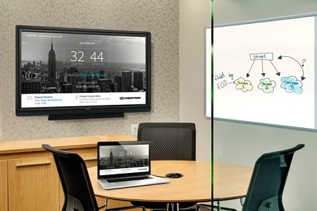
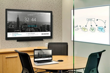
One example of a facility collaboration system. Each TCP/IP packet contains a header (field) that includes the source and destination IP addresses. These are almost always assigned by software in the sending and receiving computers. The IP address is composed of two parts, one which indicates the network of the device and another that singles out the particular computer on that network. In a future lesson, we’ll delve into how those two parts are defined. For now, we only need to know that the router relays a packet based on the part of the address that shows the destination network.
Let’s consider what steps a router takes when it receives a packet on an incoming interface. First, it strips away the Layer 2 header containing the mac addresses. These addresses are no longer needed. Their only function was to get the packet across the previous physical link. Then, using an error check value in the IP header, the router checks the integrity of the header to be sure it hasn’t been corrupted during its transit. Next, it decreases a value in the header called the hop count by exactly one to indicate that the packet passed through the router. The hop count is a value, set by the sending station, which determines the maximum number of routers a packet can pass through before the packet is judged to be lost. Next the router determines the destination address to which the packet is headed and seeks that network address in a list called its routing table. Each entry in that table will have listed a corresponding outgoing interface to use to send the packet towards its destination. Finally, the router places a new Layer 2 header on the packet and sends it using the proper outgoing interface.
So, a key element in this process is the routing table that contains the known destination networks and outgoing interfaces. So, how is it created? Routers periodically update each other on which routes they are connected to and which they can reach. The particular method by which they do this is called the routing protocol.
There is a significant difference between Layer 2 switches described in the last lesson and the routers explained in this lesson. A Layer 2 switch simply reads hardware addresses and forwards the data frame out of the proper interface. However, a router reads the packet, does an integrity check, changes the hop count and re-calculates a new error check code. Maybe that is why routers are often more expensive than switches.
Phil Hippensteel, PhD, is a regular contributor to AV Technology magazine. He teaches information systems at Penn State Harrisburg.
A daily selection of features, industry news, and analysis for tech managers. Sign up below.
