I have experienced several instances where network managers or technicians have discovered two Ethernet switches connected with more than one cable. They have reported that they had discovered a loop in their paths and consequently, removed one of the cables. Is that a mistake? Well, maybe. What motivated these individuals is the belief that loops among a set of switches is a bad thing. However, the truth is that active loops among switches are a bad thing. In other words, a loop created by a cabling arrangement is not necessarily bad; it becomes a problem if all of the cables in the loop are active. Let’s look into this.
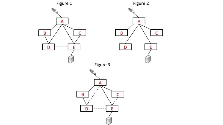
Consider Figure 1 with five switches A, B, C, D, and E, and cables connecting them as shown. If all of the connections were active simultaneously it would be bad. That’s because it contains loops. For example, A-B-D-A is a loop. If this were allowed, the first packet broadcast on the network would loop forever, even if it passed any appropriate destination. So, what needs to be done to correct this? The switches must be connected in a mathematical configuration called a tree. In a tree arrangement, each point in the network can be reached though one and only one path. Also each point in the network is connected to all other points. The arrangement in Figure 2 would be an appropriate tree.
Ethernet switches develop a tree arrangement no matter how they are connected together. The process they use is called the Spanning Tree Protocol. It works like this. Assume that the switches are cabled as in Figure 1. For convenience, we’ll suppose that power is interrupted and comes back on. Initially, all connections are activated and we have loops. However, the switches will begin immediately to send data frames out in broadcast fashion in order to accomplish two things:
- 1. The election of a root switch.
- 2. The creation of a tree that begins at that root switch.
The election of the root is based on the hardware addresses and bridge ID of the switches. The term bridge is just the former name for what we now call a switch. If a switch sends a claim to be the root but soon thereafter sees a claim from a switch with higher priority, it knows it is not the root. Eventually, one switch will win the election. Let’s say in our example, it’s switch B. Switch B then sends a frame announcing that it is the root switch. Switch A and D each hear that announcement and conclude they have a path to the root. A and D now announce that they have a path to the root by sending a packet out to all of their ports. C and E learn of this path and now have a path to the root switch, B. But when A and D hear each other’s announcement, they conclude that they are part of the loop A-B-D-A and one of the two will disable the connection from A to D. The same process will lead to two of the links among A-E, D-E and C-E being disabled. The result will be a tree such as shown in Figure 3. As you can see, the spanning tree process automatically removes loops and creates a tree arrangement.
Sometimes, redundant cable connections can provide for the tree to survive when a cable fails. So, extra connections are not necessarily a bad idea. The tree will still be established.
Phil Hippensteel, PhD, is a regular contributor to AV Technology magazine.
