Byte-Sized Lesson In AV/IP: L2 Switches/VLANs

A daily selection of features, industry news, and analysis for AV/IT professionals. Sign up below.
You are now subscribed
Your newsletter sign-up was successful
This IP lesson will focus on layer two switches, which are almost exclusively Ethernet switches. We’ll also consider how they are used to implement virtual local area networks (VLANS).

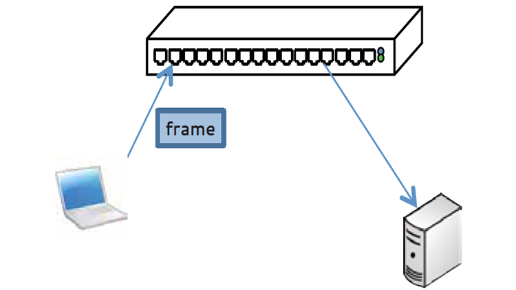
Figure 1: L2 Switch Figure 1 illustrates a notebook computer sending an Ethernet frame through a switch and on to a server. The first task is to understand how the switch knows the proper outgoing port. Within the switch is a filtering table that contains the hardware (MAC) addresses of all devices that are attached to the switch and the corresponding port to which the device is attached. So, when a frame arrives at the switch, the interface reads the destination MAC address and looks in the table for the proper outgoing port. It then relays the frame. If the frame arrives and contains an error, it will be dropped. Typically this fact is recorded for the purposes of network management.
A striking advantage of using switches is that they seem to increase available network bandwidth. In our figure we have a 16 port switch. Let’s suppose each port operates at 1Gb/sec. Can the network operate only at 1 Gb/sec? The answer is no. It can actually pass a total of 8 Gb/sec of traffic. This is because there can be eight conversations passing through the switch at any given instant.
The switch builds its address filtering table by observing the first few frames passing among devices. In our figure, the first frame from the notebook to the server will go out all ports. But, when the server responds, the switch will know that the notebook is connected to port 2 and the server is connected to port 13.

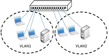
Figure 2: VLANS VLANs create networks that aren’t physically separate but act as if they are. Suppose in Figure 2 we have devices connected to ports 1-4 and we want to be able to interchange frames. Suppose also that we want the remaining devices to connect to each other using ports 5-16. If we configure the switch to use ports 1-4 as VLAN1 and ports 5-16 as VLAN2, this will be recorded in our filtering table. Now devices connected to VLAN1 cannot interchange frames with devices in VLAN2. In order to allow interaction between the devices on separate VLANS, the switch must support VLAN routing. However, when it does this it is actually performing a layer three function and will depend upon device IP addresses. More specifically, the switch will be performing this function as if it was a router.
Phil Hippensteel, PhD, is a regular contributor to AV Technology. He teaches at Penn State Harrisburg.
A daily selection of features, industry news, and analysis for tech managers. Sign up below.
