Severe noise problems such as hum or buzz often arise in audio and video systems that are in perfect compliance with National Electrical Code (NEC) and industry practices. Other systems remain trouble-free in spite of code violations, floating grounds, and other problems. Subtle factors that are rarely under the control of the system designer or installer include accidental connections to the grounding system, unknown "fixes" to building wiring, and badly designed equipment. These unknowns may conspire to make it appear that luck is a major factor, but the vast majority of noise problems are caused (or made far worse) by small ground voltage differences between the individual pieces of equipment that make up the system.
"Line-level" interconnections (as opposed to "mic-level" or "speakerlevel" interconnections) are always the most troublesome in audio systems. Because microphones and loudspeakers are rarely grounded independently of their connected cables, their interconnections rarely become part of a "ground loop." But line-level interconnects are usually between two pieces of equipment that are each independently grounded, either directly by their power cord, by rack mounting, or by a myriad of paths to other (grounded) equipment. These interconnections beg to complete ground loops. Ground loops occur because no two points in a grounding system are ever at exactly the same voltage.
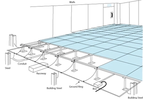
A signal reference grid is a network of copper or aluminum wires installed below a raised floor in a data center.
The most significant source of these voltage differences is magnetic induction (essentially a parasitic transformer) in the premises' power wiring. This induction creates a small voltage over the length of every safety ground wire in the premises' wiring. Since safety ground is connected to signal reference ground inside virtually every piece of audio or video equipment, the ground voltage difference causes a small power-line current to flow in signal interconnect cables. Depending on the type of interface (i.e., balanced or unbalanced) and the quality of the equipment design (i.e., CMRR of balanced inputs and freedom from "pin 1 problems"), the resulting noise problems can vary from severe to non-existent.
TWO BASIC SCHEMES
It would be wonderful if all system ground connections were equi-potential (equal voltage) regardless of ground current flow; however, in the real world, this must remain an engineer's fantasy. In the real world, ground systems consist of wires. Wires have not only resistance, but also inductance, which makes their impedance non-zero at power frequencies and rise steadily with increasing frequency. Therefore, there will likely be a voltage difference between any two physically separated points in such a grounding system.
According to Henry Ott, author of Noise Reduction Techniques in Electronic Systems, the type of grounding system you use should depend on the specific system application. "The proper ground system is determined by the type of circuitry, the frequency of operation, the size of the system (self-contained or distributed), and other constraints, such as safety," writes Ott. "No one ground system is appropriate for all applications." Over the years, two popular strategies developed to reduce system-wide ground voltage differences. According to Ott, "Normally, at frequencies below 1 MHz, a single-point ground system is preferable; above 10 MHz, a multi-point ground system is best."
"Star" or "single-point" grounding takes the approach of separating individual ground currents by forcing them to flow in different paths (wires) wherever possible. If ground currents from two pieces of equip ment share a path, the impedance of that path causes the noise to couple between them. This mechanism is called "common-impedance coupling" (which is what makes unbalanced signal interfaces so prone to noise problems).
In most systems, the single point, called the MGB (master ground bar) by some and "Mecca" by others, is the zero voltage reference ground for an entire system. Generally, this is the bus bar in the main power panel where neutral, safety ground, and earth ground are bonded as required by NEC. While the voltage at this connection point may rise above zero volts with respect to earth ground under power fault conditions, the entire system will also rise to the same voltage. This minimizes transient currents between pieces of equipment due to lightning or power surges.
For obvious reasons, it would be great to have Mecca as close as possible to the audio system equipment. Only a transformer configured as a separately derived system per NEC can establish such a new N-G bond to improve system noise. "Technical power" using isolated-ground outlets is often part of a single-point grounding scheme, where the intent is to keep unknown currents that may be flowing in a metallic conduit from flowing in the system safety ground wiring. Star grounding is very well suited for audio systems since 60 Hz and its harmonics are in the audio signal frequency range, and audio dynamic range requirements are often extremely high. Star grounding is favored (at least in the U.S.) for audio and most AV systems.
"Mesh" or "multi-point" grounding interconnects everything with a network of ground wires that attempt to approximate an equi-potential ground plane at both low (60 Hz) and high (radio) frequencies. Mesh grounding has been traditionally favored for higher-frequency systems such as IT or telecommunication systems worldwide. Although it generally can't reduce power frequency voltage differences as well as star grounding, such low frequencies are "out of band" and of little concern in highfrequency systems. However, mesh grounding is also being promoted by many Europeans as the "preferred solution" for audio systems.
At least one highly respected acoustical consultant clearly sees the potential for conflict. According to Kenneth Fause, principal consultant with AV consulting firm Auerbach Pollock Friedlander, "The major difference between IT/telephone and AV is dynamic range. A dynamic range of 20 to 40 dB may be adequate in the IT context. A dynamic range of 120 to 140 dB may be desired in some practical AV applications. The Ethernet physical layer is differential, and the signaling issue is detection of change of state. This is intended to be fairly robust on a noisy channel. Worst case, Ethernet backs off and tries again. A signal reference grid at gigahertz frequency must be on the order of 25mm [a grid of 1-inch squares]. Not too practical at an AV system scale.
A "signal reference grid" (SRG - see figure) is a very popular version of the mesh grounding technique. It is a network of copper or aluminum wires or straps typically arranged in a 2x2-foot grid and supports a raised floor of removable tiles. The tiles are usually slightly conductive to help control static electricity build-up. Power and signal cabling is routed under the floor and the space sometimes serves as a conduit for air conditioning as well. This kind of SRG has been used for over 30 years in data processing centers and was effectively standardized in 1983 when the U.S. Government published FIPS PUB 94, "Guideline for Electrical Power for Automatic Data Processing Installations." At that point in time, "high-speed" computers used 20 MHz clock frequencies. To make matters worse, most data interfaces were unbalanced (RS-232, parallel ports, or backplane) and notoriously susceptible to ground voltage differences. The noise problems were real and the SRG was an important part of an effective solution. But today computers run at least 100 times faster and use balanced data interfaces (Ethernet, RS-485, etc.) that are much less susceptible. Increasingly, data centers are now being constructed on slab floors where it would be difficult if not impossible to install an SRG under the floor.
So far, data centers installed without SRGs have experienced no adverse effects on the operation of the IT equipment, leading some technical experts to questions the need for SRGs. Yet, in spite of evidence that mesh grounding is increasingly unnecessary, it is still often specified today - presumably to eliminate problems with so-called "sensitive" equipment.
Modern AV systems, and the equipment itself, have evolved over the years into hybrid mixture of "low-frequency" analog and "high-frequency" digital. As the frequency of digital signals has rapidly increased, grounding methods like the SRG have become essentially obsolete. Saavy manufacturers are now making high-frequency noise control an issue of internal equipment design rather than system grounding.
Bill Whitlock is president of Jensen Transformers, Inc., and a leading authority on matters relating to power systems, grounding, and signal integrity. He can be reached at whitlock@jensen-transformers.com.

