Probably the most common network interconnection device in industry networks are layer 2 switches. We often refer to them Ethernet switches because the vast majority of them have only Ethernet interfaces. The most important characteristic of this type of switches is that they relay each frame from an input port to an output port based on the layer 2 addresses in the frame. For Ethernet, these are the hardware mac addresses.

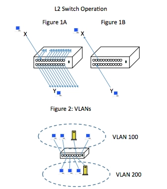
Let’s say we are using a 24-port Ethernet switch. It can support 12 data flows simultaneously since it takes a pair of ports to define a flow. As soon as a switch is powered “on,” it begins to record the destination addresses, the source address and the ports where each frame received. When a particular pair of addresses are seen travelling in the reverse direction, the switch learns which ports are the proper exit ports to reach each destination. For example, in Figure 1a, a frame is received on port 3 with the source address X and destination address Y. Since the switch does not now where the destination will be, it forwards the frame to all ports. The frame will thus reach its target station. Shortly thereafter, a frame is received on port 13 with the source address Y and destination address X. The switch now knows that the port needed to reach X is port 3 and that port 13 can be used to reach Y. It places these addresses and the corresponding outgoing ports in a table called the filtering table. From that point forward, as seen in Figure 1B, from that point forward, frames destined to station X will be relayed out port 3 and frames destined for Y will be sent out port 13.
We’ll discuss how switches prevent the possibility of a loop in the set of paths, in a future lesson. But for now it is important to note that links between switches may be disabled intentionally to prevent such loops.
So, what is a VLAN? It’s called a virtual local area network because a group of switches appear to be physically connected to make one network. However, the operation of a single switch can actually create two separate networks. Look at Figure 2. The devices attached to ports 1,2,7, and 8 can communicate through the switch because they belong to a group called VLAN 100. The devices in the second group attached to ports 3,4, 5, and 6 can communicate because they belong to a second group called VLAN 200. Nevertheless, no device in one group can communicate with a device in the other group. Separation is accomplished by placing a tag containing the VLAN ID in each frame sent within the group. Setting up this configuration is done within the switch. A good application of this idea is to separate video devices, such as cameras and video players, from data devices like Windows servers and application servers.
Phil Hippensteel, PhD, is a regular AV Technology magazine contributor. He teaches information systems at Penn State Harrisburg.
