Deep Dive on Foundational AV/IT: OSI Model
If you have anything to do with networked AV and you're not well-versed in the OSI model, we've got you covered. You will learn the fundamental ideas around getting data from host A to host B over a network using the 7 Layers of the OSI model. Part of Paul Zielie's Deep Dive Series

A daily selection of features, industry news, and analysis for AV/IT professionals. Sign up below.
You are now subscribed
Your newsletter sign-up was successful
Why Learn the OSI Model
A lot of people quietly groan when I start to talk about the Open Systems Interconnection (OSI) model. I like to think that it’s because they haven’t really been properly introduced to it, and not because they find my nuanced discussion of the subject to be a bit long-winded, and maybe an inappropriate topic for a baby shower.
The official definition of the OSI model goes something like:
The Open Systems Interconnection model (OSI model) is a conceptual model developed by the International Organization for Standardization (ISO) as ISO/IEC 7498-1:1994. It “provides a common basis for the coordination of standards development for the purpose of systems interconnection, while allowing existing standards to be placed into perspective within the overall reference model.”*
* ISO/IEC 7498-1:1994, Summary
Yada, yada, … It’s a big, old, standard about creating standards. If you want to read it, it can be downloaded at no charge from the ISO, but their free version is an unsearchable scan. I prefer the more obscure, OG, original pressing, from the International Telecommunication Union (ITU, formerly the CCITT) which developed it jointly with the ISO/IEC. The content is the same, but it is a searchable pdf. ITU-T Rec. X.200,
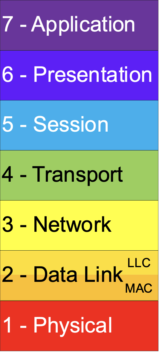
Let’s start with the idea of a model. A model is the representation of something real. A model airplane represents an airplane, it has model wings, a model cockpit, model landing gear, etc. all put together to represent a plane. A conceptual model is a representation of a system, but instead of real parts to glue together, it is made up of a collection of distinct concepts. Concepts are mental pictures of something formed from key attributes and distinct concepts clearly separate and different from each other.
Now we are getting somewhere. In the OSI standard, they list the principles used to determine the seven layers in the Reference Mode. (ISO/IEC 7498-1:1994, Section 6.2). Among those principles are:
Principal (6.2.1 c): Create separate layers to handle functions that are manifestly different in the process performed or the technology involved.
A daily selection of features, industry news, and analysis for tech managers. Sign up below.
Principal (6.2.1 d): Collect similar functions into the same layer.
Principal (6.2.1 e): Select boundaries at a point which past experience has demonstrated to be successful
This means a group of very smart people got together and spent a lot of time, breaking this complex subject into digestible, single-function chunks with at rack record of solving problems.
While the OSI model was developed to create interoperable standards, what it has developed into is an organized way of thinking and communicating about networks. If you want to do either of those things the value of internalizing the OSI model runs from helpful to critical (Technical literacy is a spectrum)."
—Paul Zielie
In real life this allows us to limit the scope of a problem to a subset of things that could go wrong. It is so useful that it has become the standard adjective for describing functional scope in a network. If someone says, “That’s a layer 3 problem” the (OSI literate) listener knows that it involves IP addressing or routing. More importantly, it eliminates the cables, the switches, and anything in the application beyond IP address configuration.
In this article, I will be discussing the fundamental ideas around getting data from host A to host B over a network using the 7 Layers of the OSI model. Anything remotely specific about methods or protocols is just an illustration. I hope that this information will help you in digesting some of the deeper dives.
> OSI Concept (Layer to Layer Communication)
Principal (6.2.1 j): Allow changes of functions or protocols to be made within a layer without affecting other layers.
Principal (6.2.1 k): Create for each layer, boundaries with its upper and lower layer only.
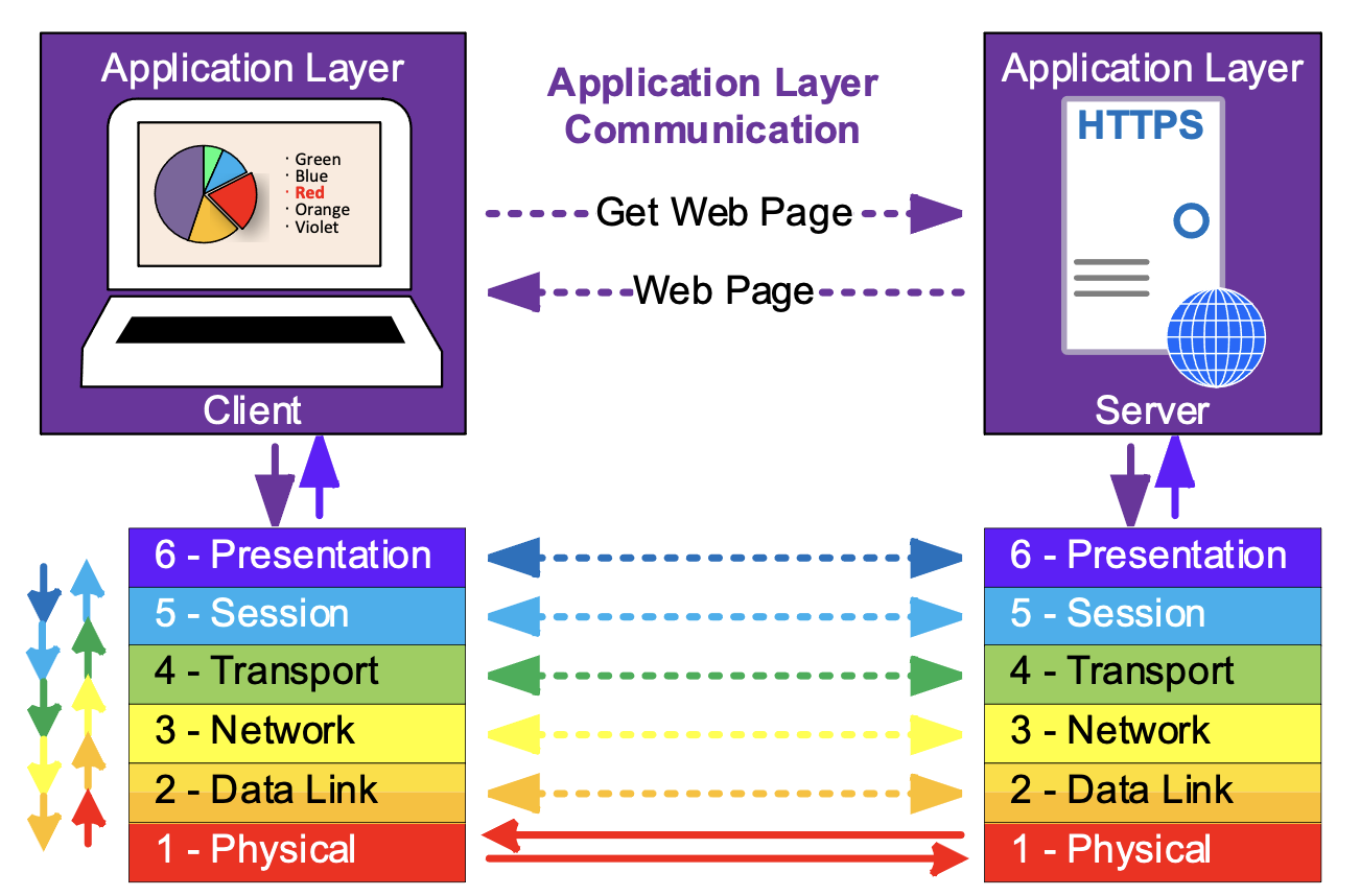
When two hosts are communicating across a network, each layer is responsible for addressing and communication with only the corresponding layer of the other host.
The dotted arrows show the functional communication of the layers, while the solid arrows show the actual path through the model.
Each layer serves the layer above it to facilitate the communication between the hosts at the higher layer and is served by the layer below it.
No individual layer needs or cares to know about the entire OSI stack. It only needs to know how to communicate with the corresponding layer on the other device and any adjacent layers on its own device.
Because of this, the OSI layers are modular. Each layer operated according to a protocol, a standardized set of methods supported by both hosts. Protocols can be substituted within a layer, without having to make changes to all the other layers, the application data can be transported across a wired network or wireless network, just by changing the layer 2 protocol (and swapping wires for radios), without any changes to the higher layers.
LAYER 7 - Application Layer
The Application Layer enables the user, which could be person, or automation, to perform a task across the network. The application layer is focused on the task at hand and is not really concerned with the network, other than the fact that it needs to communicate across the network to accomplish the task goals. There may be several “helper” application layer protocols used to assist the main application in its operation.
Examples of Layer 7 protocols include:
Domain Name System (DNS) translates human-centric domain names (like avnetwork.com) into the IP addresses used by Layer 3 (the Network Layer).
Simple Mail Transfer Protocol (SMTP) is a protocol used in sending and receiving email
Session Initiation Protocol (SIP) is a signaling protocol used for initiating, maintaining, and terminating communication sessions that include voice, video
HyperText Transport Protocol (HTTP) transmits data including content and formatting between a web server and a client.
Real Time Streaming Protocol (RTSP) coordinates and controls the transmission of AC streaming sessions.
> OSI Concept (Abstraction)
Principal (6.2.1 h): Create a layer where there is a need for a different level of abstraction in the handling of data, for example morphology, syntax, semantics.
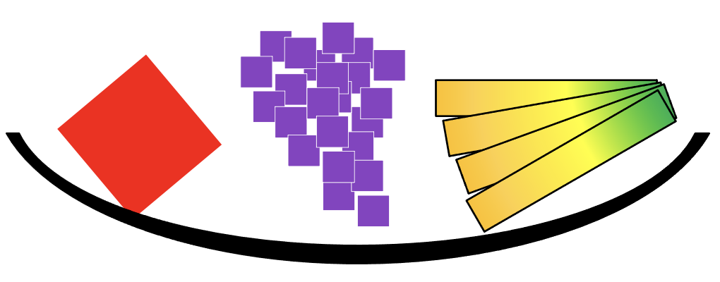
Abstraction is about representation of fundamental qualities of a thing. My abstract illustration of a bowl of fruit does not reproduce the image of a bowl of fruit, but (hopefully) represents enough of the essence of “fruitiness” and “bowl-iness” to be understood.
It is the same way in computing, abstraction is the process of describing a class (a group of similar things) in two parts; behavior, the common features or attributes and state, the values associated with the behavior. An object, an individual member of the class, can be differentiated from other objects, just describing the state. In my bowl of fruit, I used color, size, aspect ratio, the number of elements, and the relative position of elements, to convey fruit. The state (red, medium, square, 1, N/A) defines the apple, although I would have accepted tomato as an answer (it’s a fruit).
Abstraction allows us to separate “what is happening” from “what are we doing” As we work through the layers, we are concerned with what they do and why they do it. Later, this will help us as we talk about the specifics (what is happening).
LAYER 6 – Presentation Layer
The Presentation Layer is concerned with the syntax (the specific order) and semantics (the meaning) of the information exchanged between two systems.
Data Format Translation: formatting the data that layer 7 needs to send across the network into a format that can be understood by the receiving device and translating the data received back into a format used by the application.
Remember, each layer is only concerned with communicating to the same layer on the other device. The application layers Applications usually exchange information in the form of character strings, numbers, etc. The presentation layer changes these formats to and from bit streams, a sequence of bits, which encode the higher-level content into a sequence of bits suitable for transmission by the lower levels.
For example: A document being transmitted has words, made up of letters which could be converted to ASCII (American Standard Code for Information Interchange), which encodes English language characters into 8 bits, or Unicode, an international encoding standard for use with different languages and includes emojis. Additionally, information about fonts and formatting has to be included so the document is able to be re-created at the receiver. This is a specific use of abstraction.
Other optional responsibilities of the presentation layer include the following which could also be accomplished at other layers, or omitted.
Multiplexing/Demultiplexing (Mux/Demux): Multiplexing combines multiple data types used separately in the application into a single bitstream. For example audio and video could be sent as two separate bitstreams or combined into a single bitstream for delivery across the network.
Encryption\Decryption: Encryption transforms the original information to a format which renders the data unreadable by unauthorized devices before sending it out over the network. Decryption reverses the original process to transform the data back to its original form.
Compression\Decompression: Data compression reduces the number of bits which need to be sent across the network in a way which allows the receiver to recover the original data(decompression). Data compression becomes particularly important in the transmission of multimedia such as text, audio, and video.
> OSI Concept (Process Separation)
It is important to differentiate between an application, like an IPTV player, which is really just a program or group of programs, and the application layer interfaces.
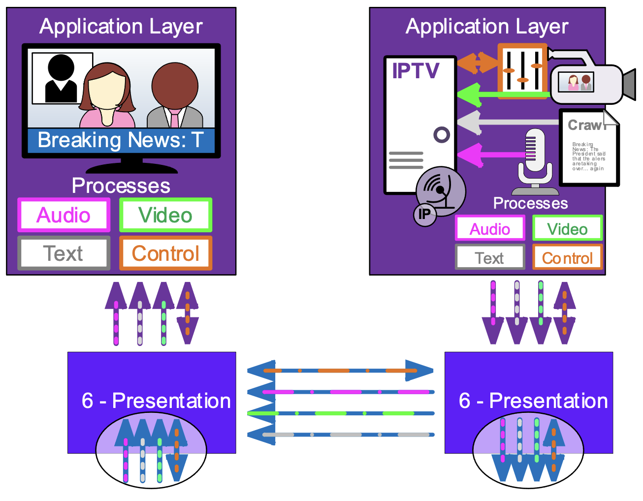
A program running on a device may require multiple network connections to send or receive different data types, or even multiple versions of the same data type. This program will have multiple processes passing data to the lower levels. A network process passing through the OSI stack is atomic, it stands on its own, without regard to other processes and requires that all the components are working correctly to succeed.
LAYER 5 - Session Layer
The Session Layer creates a semi-permanent connection between individual process on the hosts. Semi-permanent means that it has a duration longer than a single message, allowing for more efficient ongoing communication. It provides services required to establish, control, maintain and recover the session.
Session Establishment: This is the agreement between the hosts that there will be communication and what the rules of the communication will be. These rules could include authentication and authorization of the communication, information about the network methods to use like whether the communication will be half duplex (one way at a time) or full-duplex (two ways at a time) mode. The specific rules used may be negotiated or fixed depending on the protocol.
Control and Maintenance: The Session Layer controls the dialog (two way information flow) between the hosts. I could be a simple “it’s your turn to talk” during a half-duplex session or letting the other host know that it is ready to receive more information. Session control also includes the ability to close the session when it is no longer needed allowing both sides to free the session resources for other uses. The session must be maintained, this often means sending periodic “keep alive” message during times there is no data to pass, so that it doesn’t timeout and drop.
Synchronization: The session layer allows a process to add checkpoints (synchronization points) into a stream of data. These allow a dropped session to be re-established and continue the data transport at the last checkpoint, rather than having to start over.
> OSI Concept (Addressing)
Part of the magic that happens in the OSI model is that each layer keeps the various data flows sorted and everything gets to the right process. This is accomplished by having an addressing scheme for each layer which is appropriate for the (scope) responsibilities of the layer.
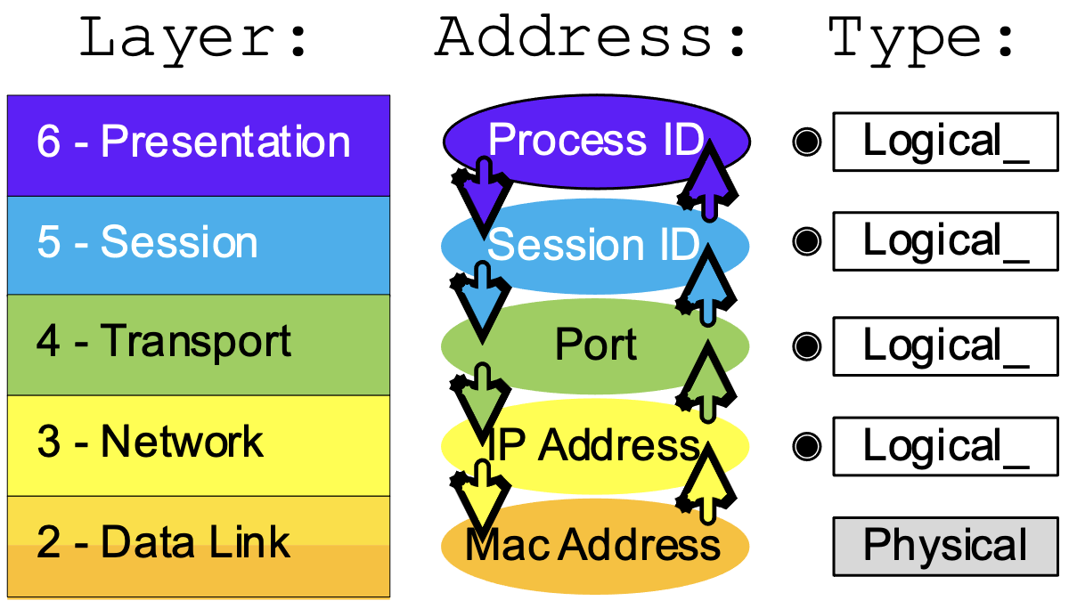
There are two types of address used Logical Addresses and Physical Addresses. Logical addresses are assigned as required for the task. For example: The layer 5 addressing, the Session ID, is assigned when there is data to be sent across the network and deleted when the session is over. Each data session running on a device has a unique ID. Physical Addresses are tied to the device and cannot be (easily or casually) changed.
When data from a process is being transmitted each layer passes the data to the next lowest level. It also includes the Source Address (local address) and Destination Address (the address of the other host) associated with the data for that layer. When data for a process is being received, the source and destination addresses are forwarded along with the data for that layer from the layer below.
LAYER 4 – Transport Layer
The Transport Layer is responsible for process-to-process delivery. This means that layer 4 is responsible for separating the bulk data that may be coming in from a remote host and making sure it is forwarded to the correct process. The most common layer 4 protocols, TCP (Transmission Control Protocol) and UDP (User Datagram Protocol) accomplish this by assigning a unique address (within the host) called port number to each session initiated by the host. This port number is forwarded along with the data to the receiving side, so it knows which port is associated with the session.
Other, less common transport protocols which do not include addressing only allow a single process to use that protocol.
The transport layer is also responsible for Segmentation and Re-assembly: Ethernet is a packet-based transport, it allows multiple hosts to share the network by limiting the size of data which can pe transferred at one time and taking turns. Layer 4 divides a larger bitstream into transmittable segments. On the sender side the bitstream is reassembled at receiver side. Some protocols like TCP assign each segment a sequence number so the receiver knows if a segment is missing or received out of order.
The segment size is chosen by layer 4 based on the requirements of the process and the network. Process like real-time audio will have small segment sizes to limit the latency caused by waiting for an incoming data to fill, while other processes will want large packets to minimize the number of packets. The network imposes minimum and maximum sizes that can be sent over the network. The minimum size of an IPv4 packet is 68 Bytes, the minimum size of an IPV6 packet is 1280 Bytes. The maximum size is called the Maximum Transmission Unit (MTU) and is a property of layer 2 transport. The Standard MTU for Ethernet is 1500 Bytes.
Other (protocol dependent) responsibilities of the transport layer include the following:
Connection control: The transport layer can be either connection oriented or connectionless. connection-oriented protocols like TCP there is communication throughout the session about the status of the data transfer. This communication allows connection-oriented protocols to provide flow control and error correction. Connectionless protocols like UDP just send the data and do not expect a response in the layer 4 protocol. Services like flow control and error correction could be provided at the application layer.
Flow control: The transport layer can provide for end-to-end flow control. Flow control limits the amount of data sent at one time, resulting in the transmitting side waiting until the receiving side signals that it is ready to process more data.
Error correction: The transport layer can provide for error correction. The transmitting host includes information like sequence numbers and checksums (numbers derived from the data that indicate if it has been changed). If the receiving host determines there is an error (damage, or loss), it signals the transmitting host to re-transmit the lost or damaged packets. It also checks for duplication and out of order packets, discarding extra packets and re-ordering before re-assembly and passing the data to the upper layer process.
> OSI Concept in Real Life (Encapsulation)
Protocols need to transfer meta-data (data about data), like addresses and protocol states (current conditions) along with the data from the process.
We also discussed that the OSI layers are modular, protocols used by a layer can be swapped (sometimes during the actual data transmission).
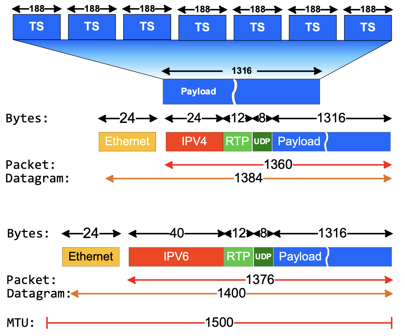
In real life these two things are accomplished using a technique called encapsulation. The protocol for each layer creates a header, containing the protocol meta-data and adds it to the input it received from the layer above it. Each layer
The Illustration shows a single Ethernet Datagram containing a portion of a larger MPEG Transport Stream (TS). Transport Stream multiplexes audio, video, and meta-data into a single bitstream, logically divided into 188 Byte TS Packets. Layer 4 (Transport Layer) receives the bitstream and creates a segment with 1316 Bytes of the bitstream. This is the payload which will reassembled int a bitstream at the receiving host and be passed to the application process.
Each subsequent layer adds the header associated with its protocol. In this case there is a second layer 4 header for Real Time Protocol (RTP), which is a helper protocol adding features required for streaming media which are not in the UDP protocol. Notice that we have shown encapsulations with Layer 3 (Network Layer) protocols IPv4 and IPv6. The sizes of individual headers are set by the protocol and is not fixed by the layer. The IPv6 header is larger because the IPv6 address is 128 bits compared to the 32-bit IPv4 address.
On the receiving side de-encapsulation reverses the process, each layer, starting at Layer 2 (Data Link Layer) receives the encapsulated data and removes the header for its layer, before passing it to the next layer. Because each header contains the source and destination address for the layer, it is correctly forwarded up the OSI stack to the proper process.
LAYER 3 - Network Layer
The Network Layer is responsible for the network-to-network delivery of all messages. This includes figuring out where the destination actually is. It could be local, or on the other side of the world. Layer 3 releases the sending host from the task of knowing the network path to the receiving host, placing that responsibility on the network infrastructure. It does this using two primary methods addressing and routing. This gives us another device type, the Layer 3 device, or router.
Logical addressing: The network layer adds a header to the packet coming from the upper layer that, among other things, includes the logical addresses of the sender and receiver. Unlike the layer 4 address which is concerned only with the process so it only needs local context (how it fits into its purpose), the layer 3 address is global in scope so the address assignment needs have a much larger context so it can be found. The context of a (US) postal address is [country>state>city/zip code>street>number]. This works well because buildings don’t move around much.
Layer 3 addresses in hosts are configured with a more limited context: [me>my location>everywhere] else. Spoiler alert: that means IP [address>subnet mask>default gateway]. If I am only delivering mail within a city, I don’t really need the state and country portions of the address other than to know that if it is not my city, then put it in the basket by the truck and someone else takes care of it.
Routing: Layer three addressing is subdivided into (millions of) local networks. Internetworking, the practice of interconnecting multiple computer networks so that data can be passed between them is performed by Routers (the truck in the previous metaphor). Each local network is attached to a router which is also attached to networks with other routers and as a group, are responsible for finding the local network of the destination device.
Layer three can also provide additional services including quality of service parameters and error notification.
LAYER 2 - Data Link Layer
The Data Link Layer is responsible for providing connection oriented and connectionless data transfer within a local network. It can provide (connectionless) broadcasts which forwards messages
Principal (6.2.1 m): Create further subgrouping and organization of functions to form sublayers within a layer in cases where distinct communication services need it.
Layer 2 has a split role as the interface between the software and hardware aspects of network transmission. For this reason, it is usually thought of with two sub-layers.
The upper sub-layer, called Logical Link Control (LLC), primarily responsible for framing the data for transmission on the physical network, this includes adding a header with layer 2 source and destination address, as well as a preamble for clock sync and an End of Frame (EoF) footer.
Depending on the protocol, the Logical Link Control (LLC) and provide other services.
Error control adds reliability to the physical layer by adding mechanisms to detect and retransmit damaged or lost frames. It also uses a mechanism to recognize duplicate frames.
Flow control: If the rate at which the data is absorbed by the receiver is less than the rate produced at the sender, the data link layer imposes a flow control mechanism to prevent overwhelming the receiver.
Layer 2 is designed to allow multiple upper sub-layer protocols to run simultaneously on a host. For example, there are two different LLC protocols commonly used in Ethernet, IEE 802.2 and Ethernet II. (Two, not eleven). There are other, upper sub-layer protocols for other physical interfaces, for example, Bluetooth uses Logical link control and adaptation protocol (L2CAP).
The lower sub-layer, the Medium Access Control (MAC), provides local, globally unique addressing and permission to transmit via collision detection or other means.
LAYER 1 - Physical
The physical layer coordinates the functions required to carry a bit stream over a physical medium. It deals with the mechanical and electrical specifications of the interface and transmission media. The physical layer is also concerned with the following:
Representation of bits: The physical layer data consists of a stream of bits (sequence of 0s or 1s) with no interpretation Data rate: The transmission rate—the number of bits sent each second—is also defined by the physical layer
Synchronization of bits: The sender and receiver must not only use the same bit rate but must also be synchronized at the bit level.
Line configuration: The physical layer is concerned with the connection of devices to the media. In a point to-point configuration, two devices are connected together through a dedicated link. In a multipoint configuration, a link is shared between several devices.
Physical topology: The physical topology defines how devices are connected to make a network. Transmission mode: The physical layer also defines the direction of transmission between two devices: simplex, half-duplex, or full duplex.
Conclusion
While it may seem like a lot, taking the time to frame your thoughts about networking within the context of the OSI model will help you see where it fits into the bigger picture. You can’t really understand what to do until you understand what you are trying to do. In our next installment, we will put this into practice, looking at what actually happens behind the scenes when data is sent across the network.

Paul Zielie, CTS-D,I is a multi-disciplined generalist with 30 years of experience designing and integrating IT, telecommunications, and audiovisual (AV) solutions.
Over the course of his career, he has had most of the roles in the AV/IT spectrum including customer/end user, IT owner, integrator, designer, managed service provider, distributor, pre-sale specifier, executive, and manufacturer. Because of this extensive real-world experience in every facet of the AV/IT lifecycle, he brings an almost unique perspective on the consequences, both intended and unintended of how product and project features are implemented.
“What I really do for a living is solve problems, little or big, with appropriate technical solutions. I believe that technology is in service to organizational goals and workflow, and not an end in itself, and use that as a guiding principle in my design efforts.”
He is a prolific writer and speaker and was the recipient of the 2015 InfoComm International, Educator of the year and was inducted into the SCN Hall of Fame in 2020. As a consulting solutions architect for AVCoIP LLC, Zielie specializes in working with AV manufacturers to create products that meet enterprise customers' IT requirements.
